Eureka AIR delivers breakthrough ideas for toughest innovation challenges, trusted by R&D personnel around the world.

Thin film solar cell scribing device and method

A technology for solar cells and thin films, applied in the field of solar cells, can solve the problems of increasing the spacing of three scribe lines, affecting the conversion efficiency of thin-film solar cell modules, and increasing the area.

Active Publication Date: 2017-06-20
西安中易建科技集团有限公司
View PDF5 Cites 2 Cited by
  • Summary
  • Abstract
  • Description
  • Claims
  • Application Information

AI Technical Summary

Problems solved by technology

In order to prevent the three scribed lines of P1, P2 and P3 from bending and intersecting each other, resulting in waste products and a decrease in the yield rate of thin-film solar cells, the usual solution is to increase the distance between the 3 scribed lines
However, the implementation of this scheme will lead to an increase in the area of ​​the "dead zone", which will affect the overall conversion efficiency of the thin film solar cell module.

Method used


Image

  • Thin film solar cell scribing device and method
  • Thin film solar cell scribing device and method
  • Thin film solar cell scribing device and method

Examples


Embodiment Construction

[0040] In order to facilitate the understanding of the present invention, the present invention will be described more fully below with reference to the associated drawings. Preferred embodiments of the invention are shown in the accompanying drawings. However, the present invention can be embodied in many different forms and is not limited to the embodiments described herein. On the contrary, the purpose of providing these embodiments is to make the disclosure of the present invention more thorough and comprehensive.

[0041] It should be noted that when an element is referred to as being “fixed” to another element, it can be directly on the other element or there can also be an intervening element. When an element is referred to as being "connected to" another element, it can be directly connected to the other element or intervening elements may also be present. The terms "vertical," "horizontal," "left," "right," and similar expressions are used herein for purposes of ill...


PUM


Abstract

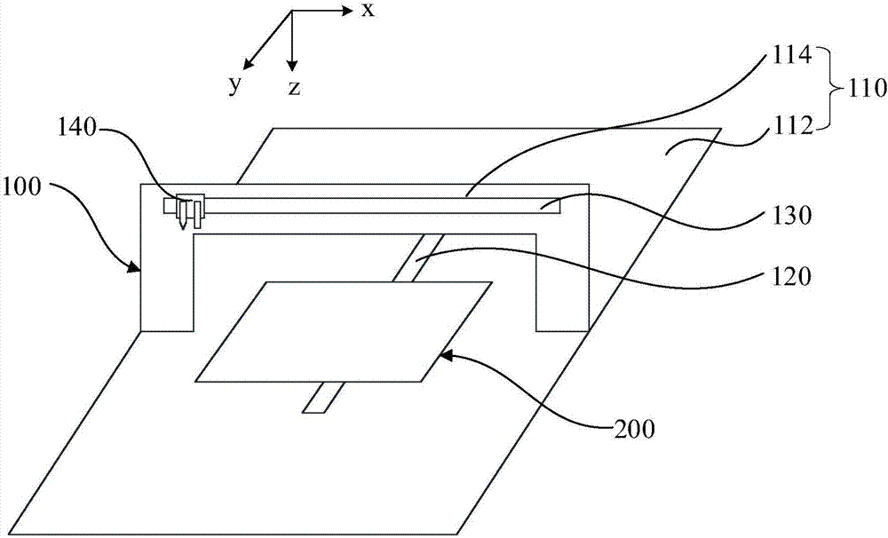
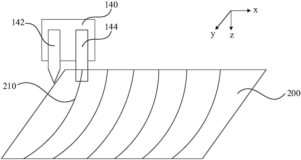
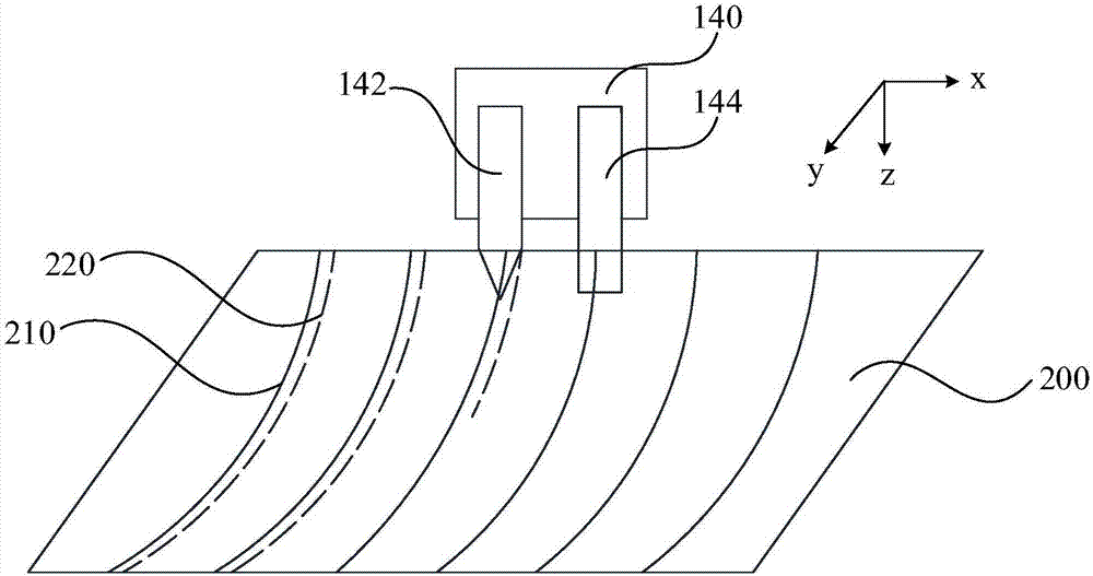
The present invention relates to a thin film solar cell scribing device and method. The device comprises a work bench, a first guide rail which is arranged on the work bench and used to move a thin film solar cell, a second guide rail which is arranged on the work bench and positioned above the first guide rail, wherein the extension direction of the second guide rail is orthogonal with the extension direction of the first guide rail and is parallel to the extension directions of multiple pre-scribing lines, a scribing assembly which is slidably arranged on the second guide rail and comprises a scribing head and a pick-up head arranged at an interval, wherein the scribing head scribes the thin film solar cell and the pick-up head can collect image information of the multiple pre-scribing lines, a processing module which is in communication connection with the scribing assembly and obtains the paths of the multiple pre-scribing lines according to the image information of the multiple pre-scribing lines to obtain the paths of the multiple scribing lines corresponding to the thin film solar cell and to control the scribing head to scribe the thin film solar cell. The device can improve the overall conversion efficiency of the thin film solar module.

Description

technical field [0001] The invention relates to the technical field of solar cells, in particular to a scribing device and method for thin-film solar cells. Background technique [0002] In order to control and increase the output voltage value, solar cells are usually made into modules, that is, multiple cells are connected in series. Segmentation between sub-cells on different functional layers is achieved by scribing. [0003] Three scribe lines are required to be introduced in the fabrication process of copper indium gallium selenide (CIGS) thin film solar cells. First of all, after the molybdenum (Mo) back electrode layer is plated on the soda-lime glass substrate, the laser is used to perform the first scribing on the surface of the Mo back electrode layer to evenly divide it into slender small cells, and the first scribing The line is marked as P1; secondly, after continuing to plate the CIGS light absorbing layer and cadmium sulfide (CdS) / zinc oxide (ZnO) buffer la...

Claims


Application Information

Patent Timeline
IPC IPC(8): H01L31/18B28D5/00
CPCB28D5/0082H01L31/18Y02P70/50
Inventor 张撷秋杨世航崔骏刘壮陈旺寿李霖
Owner 西安中易建科技集团有限公司
Why Eureka
Eureka Blog
Learn More