
Ethylene oxide waste gas treatment and energy recovery system

A technology for waste gas treatment and energy recovery, which is applied in gas treatment, combustion methods, fixed tubular conduit assemblies, etc., and can solve problems such as high safety hazards, ethylene oxide discharge into the atmosphere, and environmental pollution.

Active Publication Date: 2017-06-20
杭州博控机电设备有限公司
View PDF6 Cites 14 Cited by
  • Summary
  • Abstract
  • Description
  • Claims
  • Application Information

AI Technical Summary

Problems solved by technology

[0003] The working principle of the exhaust gas treatment system of the leaching tower is to pass ethylene oxide into the sulfuric acid solution, pass through the leaching tower, make the ethylene oxide and the sulfuric acid solution fully contact, dissolve in the sulfuric acid solution, and under the catalysis of sulfuric acid, the ring Ethylene oxide is hydrated to form ethylene glycol, which usually requires multi-stage leaching, but ethylene oxide cannot be completely absorbed, and a small amount of ethylene oxide will be discharged into the atmosphere, causing pollution to the environment
And the waste liquid generated is hazardous waste, which needs to be treated by a qualified hazardous waste treatment company, and the treatment cost is expensive
[0004] The working principle of the combustion tower exhaust gas treatment system is to directly burn ethylene oxide to generate carbon dioxide and water. The removal rate of ethylene oxide can reach 100%, and there is no pollution to the environment. However, this method requires high equipment and has great safety hazards. Because ethylene oxide is within the concentration range of 2.6% to 100%, it will explode when it encounters an open flame, and the energy is not recovered.

Method used


Image

  • Ethylene oxide waste gas treatment and energy recovery system
  • Ethylene oxide waste gas treatment and energy recovery system
  • Ethylene oxide waste gas treatment and energy recovery system

Examples


Embodiment

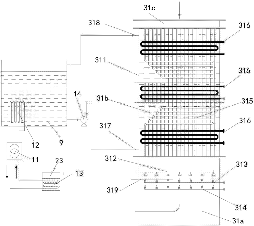
[0020] Example: refer to figure 1 with 2 . An ethylene oxide waste gas treatment and energy recovery system, comprising an ethylene oxide sterilizer 1, a tail gas absorption device 2, and an energy recovery device 3, the tail gas absorption device 2 including a water ring vacuum pump 21, a steam-water separator 22 , water storage tank 23, several combined ethylene glycol reaction tanks 25, combined spray tower 26; the upper side of the steam-water separator 22 is provided with a water inlet, the lower side is provided with a water outlet, the top is provided with an air outlet, and the bottom A drain port with a drain valve is provided, the EO waste gas outlet pipe of the ethylene oxide sterilizer 1 is connected to the inlet end of the water ring vacuum pump 21, and the gas-liquid mixing outlet end of the water ring vacuum pump 21 passes through the pipeline It is connected to the water inlet, and the water outlet is connected to the water return end on the top side of the w...

Embodiment 2

[0025] Embodiment 2: refer to image 3 . A number of fifth heat exchange tubes 37 are arranged in the central heating water tank 9, and one or more sets of air-water heat exchangers 32 are circularly connected with one side heat exchange interface of the corresponding combined air energy heat pump 33, one or more The heat exchange ports on the other side of the multiple sets of combined air source heat pumps 33 communicate with one or more sets of fifth heat exchange tubes 37 . Thus, the incinerated gas is heat-exchanged to the combined air-energy heat pump 33 through the air-water heat exchanger 32, and then transferred to the fifth heat-exchange tube 37 by the combined air-energy heat pump 33 to achieve heat exchange for the water in the central heating water tank 9. .

Embodiment 3

[0026] Embodiment 3: refer to Figure 1-3 . The ethylene oxide sterilizer processes the ethylene oxide waste gas produced by it. When sterilizing, the concentration of ethylene oxide in the cavity is about 650mg / L; the acid solution in the combined ethylene glycol reaction tank 25 passes through chemical circulation The pump is pressurized and transported to the top of the combined spray tower 26, and the acid liquid is sprayed onto the liquid uniform distributor through the acid liquid dispersing nozzle of the spray device 29. When working, ethylene oxide passes through the liquid distributor from bottom to top, and acid liquid passes through the liquid distributor from top to bottom, maximizing the contact surface area of ​​ethylene oxide and acid, so that the ethylene oxide can be maximized Dissolved in the acid solution; when burning, the ethylene glycol waste liquid passes through the chemical high-pressure pump and the electric control valve to pass the ethylene glycol ...


PUM


Abstract

The invention relates to an ethylene oxide waste gas treatment and energy recovery system. The system comprises an EO tail gas generating device, a tail gas absorbing device and an energy recycling device, wherein the tail gas absorbing device comprises a water ring type vacuum pump, a steam-water separator, a water storage tank, a plurality of combined type ethylene glycol reaction tanks and a combined type spraying tower; the energy recycling device comprises a waste liquid combustion spiral tube heat exchanger, a plurality of gas-water heat exchangers, a plurality of combined type air energy heat pumps, an activated carbon adsorption box and an induced draft fan, the waste liquid combustion spiral tube heat exchanger comprises a combustion tank, a waste liquid spraying device, a combustion-supporting gas jetting device and a compressed air jetting device. According to the invention, the waste liquid of ethylene glycol treated by the tail gas absorbing device and the ethylene oxide gas which is not absorbed by water are combusted, through automatic control, full combustion is guaranteed, and the ethylene oxide, ethylene glycol and other organic matters are completely converted into water and carbon dioxide to realize the zero emission of ethylene oxide, at the same time, a plurality of groups of heat exchangers are arranged, and the combusted energy is subjected to heat exchange application.

Description

technical field [0001] The invention relates to an ethylene oxide waste gas treatment system, in particular to an ethylene oxide waste gas treatment and energy recovery system. Background technique [0002] The main source of ethylene oxide waste gas is the waste gas produced by ethylene oxide sterilization, a low-temperature chemical sterilization method that is widely used because of its minimal impact on the product. The commonly used ethylene oxide waste gas treatment devices on the market are washing towers and incineration towers. [0003] The working principle of the exhaust gas treatment system of the leaching tower is to pass ethylene oxide into the sulfuric acid solution, pass through the leaching tower, make the ethylene oxide and the sulfuric acid solution fully contact, dissolve in the sulfuric acid solution, and under the catalysis of sulfuric acid, the ring Ethylene oxide is hydrated to form ethylene glycol, which usually requires multi-stage leaching, but et...

Claims


Application Information

Patent Timeline
Patent Type & Authority Applications(China)
IPC IPC(8): B01D53/72B01D53/78F23G7/06F28D7/00
CPCB01D53/343B01D53/72F23G7/06F28D7/00F23G2206/203B01D2259/124B01D2258/02B01D2251/50Y02E20/12
Inventor 盛奇平
Owner 杭州博控机电设备有限公司
Learn More