
A kind of rc oscillator with high oscillation frequency

A technology of oscillation frequency and oscillator, which is applied in the field of RC oscillator with high oscillation frequency, can solve the problems of increasing the occupied area of ​​the chip and not being able to significantly increase the RC oscillation frequency, and achieve the effects of reducing circuit delay, increasing oscillation frequency, and high precision

Active Publication Date: 2019-12-17
SAGE MICROELECTRONICS CORP
View PDF4 Cites 0 Cited by
  • Summary
  • Abstract
  • Description
  • Claims
  • Application Information

AI Technical Summary

Problems solved by technology

It can be seen from the above documents that the existing technology improves the precision of the RC oscillator by setting more trimming bits or adding other components (such as setting a voltage-controlled oscillator and multiple operational amplifiers, or even specially designing a comparator). To a certain extent, the occupied area of ​​the chip will be increased, and at the same time, the RC oscillation frequency cannot be significantly increased.

Method used


Image

  • A kind of rc oscillator with high oscillation frequency
  • A kind of rc oscillator with high oscillation frequency
  • A kind of rc oscillator with high oscillation frequency

Examples


Embodiment Construction

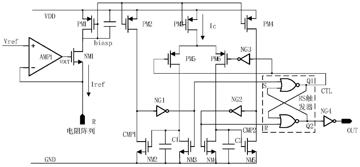
[0019] The RC oscillator with high oscillation frequency provided by the present invention will be further described below with reference to the accompanying drawings.

[0020] In order to overcome the defects of the prior art, the applicant conducted in-depth research on various RC oscillator structures in the prior art, and the applicant found that the frequency of the RC oscillator is mainly controlled by the resistance R, the capacitance C, the capacitance charging current Ic and the charging It is determined by parameters such as time delay, and these parameters are easily affected by factors such as power supply voltage and process. It is the inaccuracy of these parameters that leads to frequency errors, which in turn leads to a lower output frequency of the RC oscillator. The specific reasons are as follows:

[0021] 1. In the prior art, a comparator is used to control RC charge and discharge. The comparator delay is added to the RC time constant, and the part of the ca...


PUM


Abstract

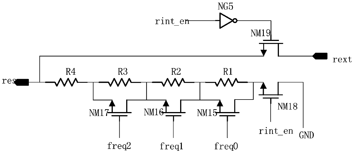
The invention discloses an RC (Resistance-Capacitance) oscillator with high oscillation frequency. The RC oscillator is characterized by comprising an operational amplifier AMP1, a resistance control unit, a first NMOS (N-type Metal Oxide Semiconductor) transistor NM1, a second NMOS transistor NM2, a third NMOS transistor NM3, a fourth NMOS transistor NM4, a fifth NMOS transistor NM5, a first PMOS (P-type Metal Oxide Semiconductor) transistor PM1, a second PMOS transistor PM2, a third PMOS transistor PM3, a fourth PMOS transistor PM4, a fifth PMOS transistor PM5, a sixth PMOS transistor PM6, a first NOT gate NG1, a second NOT gate NG2, a third NOT gate NG3, a fourth NOT gate NG4, a first capacitor C1, a second capacitor C2, a third capacitor C3 and an RS trigger. Compared with the prior art, the RC oscillator has the advantages that the technical solution adopts the structures of the MOS transistor and an inverter to replace the comparator in the prior art to control RC charge and discharge, and the switching speed of the MOS transistor can reach less than 1ns, so that the circuit delay is greatly reduced, and the oscillation frequency is obviously improved.

Description

technical field [0001] The invention belongs to the field of RC oscillators, in particular to an RC oscillator with high oscillation frequency. Background technique [0002] Clock signal is an important part of large scale digital integrated circuit. RC oscillators are widely used in on-chip clock generation circuits because of their simple structure, low cost, and ease of integration. However, in the prior art, most RC oscillators are applied to low-frequency clock sources within 20 MHz, and there are few mature technical solutions for high-frequency and high-stability RC oscillators exceeding 50 MHz. With the continuous improvement of digital processing speed, the application requirements of high-frequency RC oscillators are very large. However, the output frequency of traditional RC oscillators is affected by circuit delay, process, power supply and temperature. Increasing the oscillation frequency will greatly increase the frequency error range. , so it is difficult to...

Claims


Application Information

Patent Timeline
Patent Type & Authority Patents(China)
IPC IPC(8): H03B5/24
CPCH03B5/24
Inventor 樊凌雁袁志东范旭东
Owner SAGE MICROELECTRONICS CORP
Learn More