
A low-pressure oil passage fuel injection valve

A technology for fuel injection valves and oil passages, which is applied in the field of fuel injection valves and engine fuel injection valves, and can solve the problems of slowing down of fuel outlet speed, tortuous passages, and increased loss along the way, so as to achieve smooth oil outlet passages and reduce One-sided impact, the effect of improving the response speed

Active Publication Date: 2019-05-14
CHINA FIRST AUTOMOBILE
View PDF10 Cites 0 Cited by
  • Summary
  • Abstract
  • Description
  • Claims
  • Application Information

AI Technical Summary

Problems solved by technology

However, the scheme adopts the method of leading the dynamic return oil upwards, which has limitations. The so-called dynamic oil return is the return oil that is directly discharged from the control chamber when the steel ball of the control valve is opened. Although the pressure is low, the temperature is high, so When it is introduced into the electromagnet, the cooling effect is limited, and it even has a heating effect on the electromagnet under some working conditions; due to the large oil volume of the dynamic oil return, it generally accounts for two-thirds of the total oil return Above, leading it up to the electromagnet will make the channel of the dynamic oil return flow more tortuous, the distance will be longer, the loss along the way will increase, and the resistance of the discharge will increase.
If the dynamic oil return cannot be discharged quickly, the oil outlet speed of the control valve steel ball in the control chamber will slow down when the control valve steel ball is opened, which will increase the opening delay of the fuel injection and slow down the response
In addition, the dynamic oil return of this scheme is injected into the armature chamber from the oil hole on one side of the control valve, which will cause a one-way impact on the armature, causing a certain imbalance in its movement, thus affecting the injection accuracy of the injector.

Method used


Image

  • A low-pressure oil passage fuel injection valve
  • A low-pressure oil passage fuel injection valve
  • A low-pressure oil passage fuel injection valve

Examples


Embodiment 1

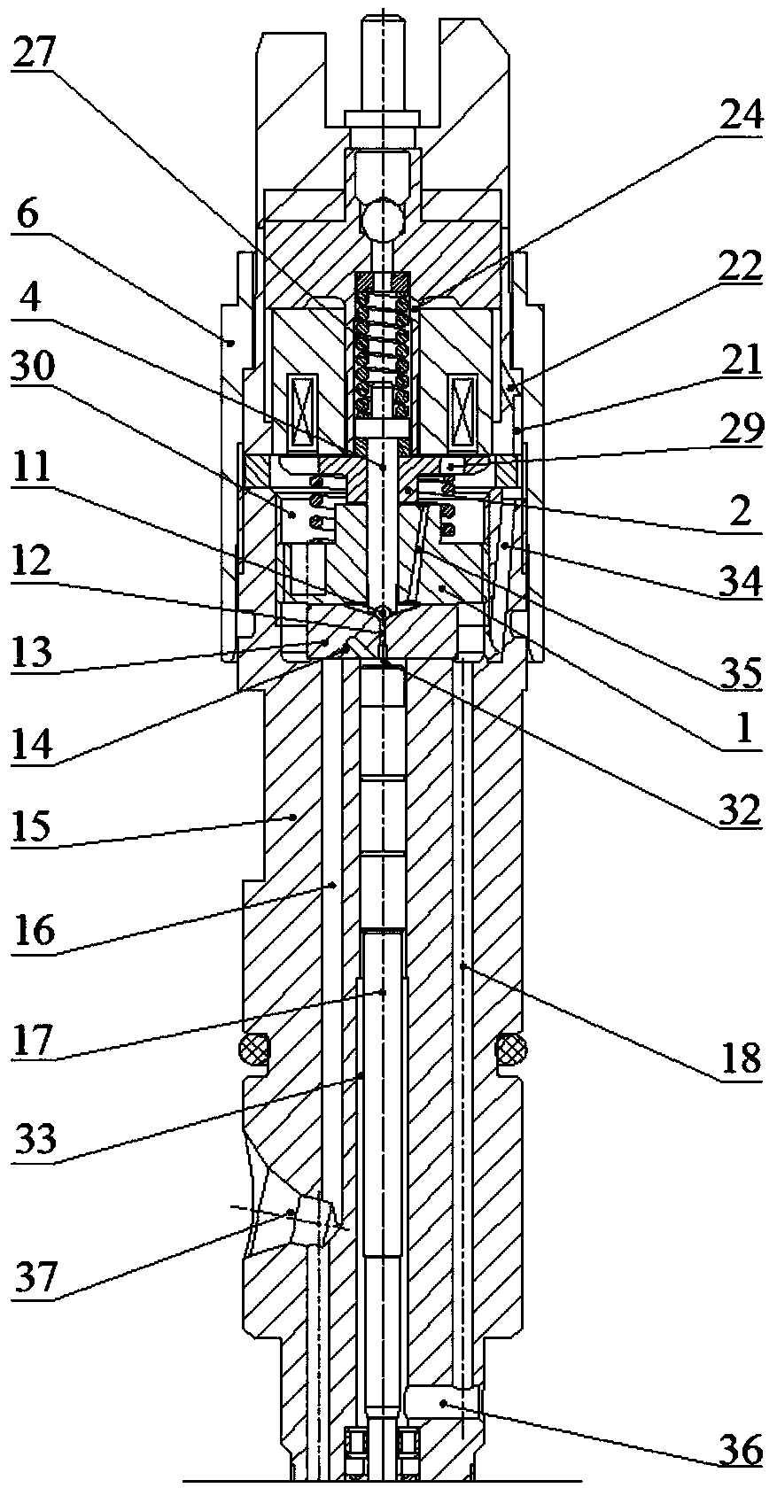
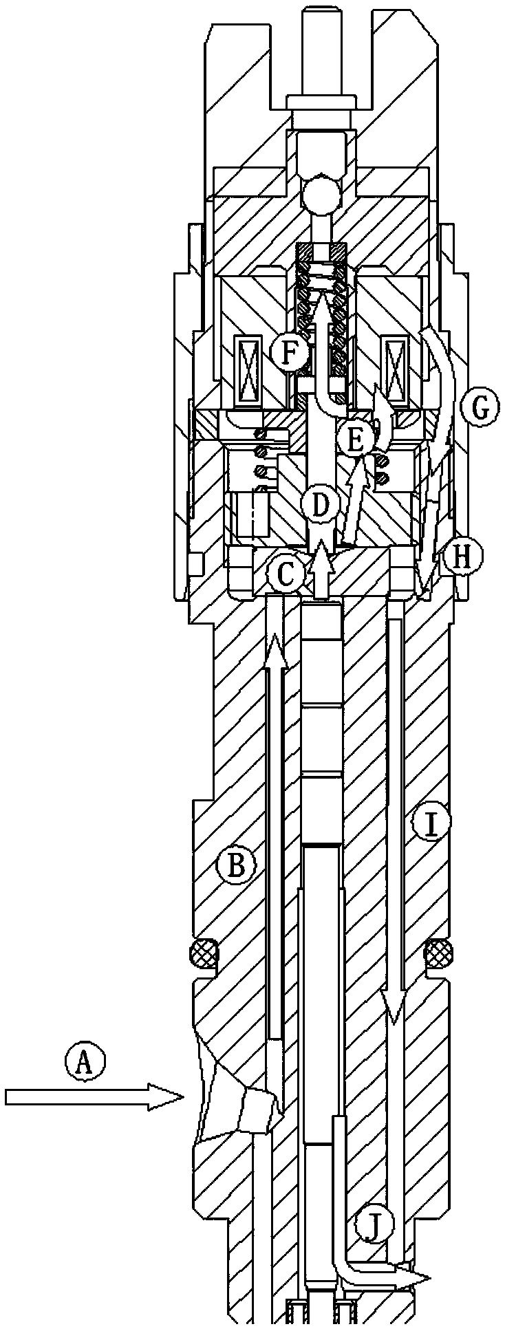
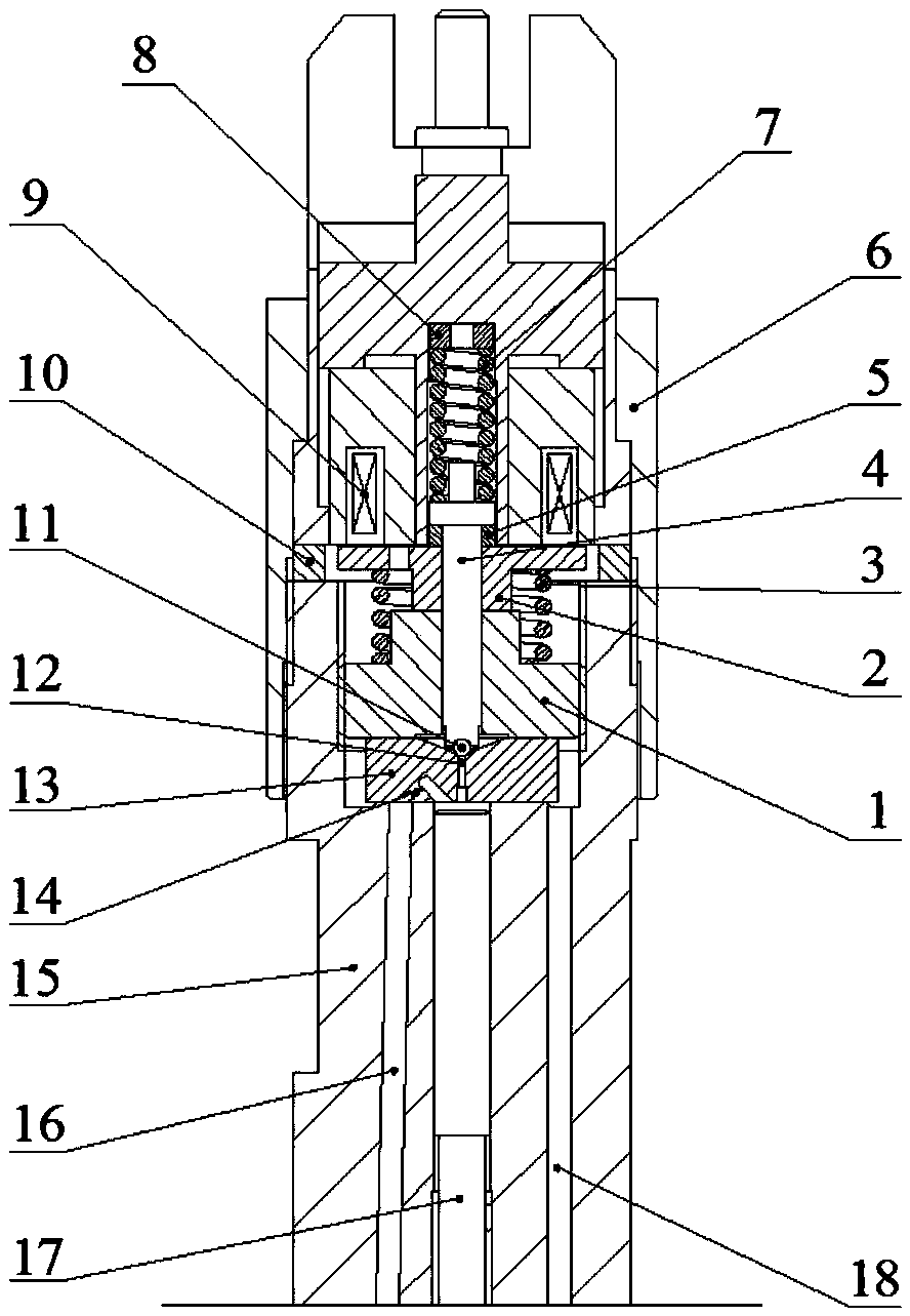
[0046] The direction of the low-pressure oil circuit in the first embodiment is: after the electromagnet is energized, the armature 2 is attracted to drive the armature rod 4 and the steel ball 11 to move up, and the high-pressure oil in the control piston chamber 33 is discharged from the oil outlet orifice 12. The control valve seat drainage groove 38 on the bottom surface of the control valve seat 1 flows into the throttle orifice chamber 43. Since the main oil return hole 18 directly communicates with the outside, the pressure in the hole is relatively low. The oil hole 18 drains and directly discharges from the injector. During the operation of the injector, the high-pressure oil stored in the upper cavity of the control piston cavity 33 will leak into the lower cavity of the control piston cavity 33 through the gap between the control piston 17 and the injector body 15, forming a static state. The oil return, the static return oil enters the radial blind hole 19 through t...


PUM


Abstract

The invention relates to a fuel injection valve which is particularly used for injecting high-pressure fuel from a high-pressure accumulation cavity into a diesel engine cylinder in a high-pressure common rail injection system of a diesel engine, and belongs to the technical field of engine fuel injection. The fuel injection valve comprises a control valve assembly, an electromagnet assembly, an electromagnet pressing cap, an electromagnet spring, a throttling orifice plate, a fuel injector body, a control piston and an ejector pin, wherein the throttling orifice plate is arranged in a throttling orifice plate chamber of the fuel injector body; the throttling orifice plate is located at the bottom of a control valve seat; a fuel injector body fuel return channel and a main fuel return hole which are staggered from each other are formed in the fuel injector body; and the upper end of the main fuel return hole is connected with the throttling orifice plate chamber. According to the fuel injection valve, a low-pressure fuel path system of the fuel injection valve is optimized; by a method of introducing static returned fuel with relatively low temperature to an electromagnetic actuator, the electromagnet assembly is effectively cooled; and meanwhile, by flowing of the returned fuel, a large quantity of harmful bubbles accumulated in an electromagnet and armature chamber can be brought out of the fuel injector body.

Description

Technical field [0001] The invention relates to a fuel injection valve, in particular to a high-pressure common rail injection system used in a diesel engine, injecting high-pressure fuel from a high-pressure accumulating cavity into a diesel engine cylinder, and belongs to the technical field of engine fuel injection valves. Background technique [0002] In order to meet increasingly stringent emission regulations, high-pressure common rail has increasingly become a key technology for energy saving and emission reduction of diesel engines. As a core component of common rail technology, electronically controlled injectors need to further improve their reliability, stability, injection accuracy and response speed . As the control component of the fuel injector, the electromagnetic actuator needs to work for a long time under the energized condition, which causes the electromagnet to be in a high temperature state. Excessive temperature will cause the material of the electromagnet ...

Claims


Application Information

Patent Timeline
Patent Type & Authority Patents(China)
IPC IPC(8): F02M51/06F02M61/18F02M63/00
CPCF02M51/061F02M61/18F02M61/1853F02M63/0017F02M63/007
Inventor 顾小磊金昱森俞建达郑冰
Owner CHINA FIRST AUTOMOBILE
Learn More