


Quick Research
Generate reliable direction feasibility study reports for your R&D in just a few steps.

Technical Q&A
Discover and master advanced knowledge NOW. Basics, ideas, possibilities, all at once.

Find Solutions
As an expert in R&D theories, this can generate solutions to your technical problems instantly.

Evaluate Feasibility
Analyze your overall solution with one click, know your potential R&D risks in advance.

Monitor Landscape
Get weekly tech updates, stay abreast of the latest tech innovations and key insights.
Electrochemical system used for achieving CO2 capturing and mineralization
An electrochemical and electrolyte technology, applied in the field of electrochemical systems, can solve problems such as complex system structure, achieve the effects of simple system structure, easy modular design, and huge application prospects
- Summary
- Abstract
- Description
- Claims
- Application Information
AI Technical Summary
Problems solved by technology
Method used
Image


Examples
Embodiment 1
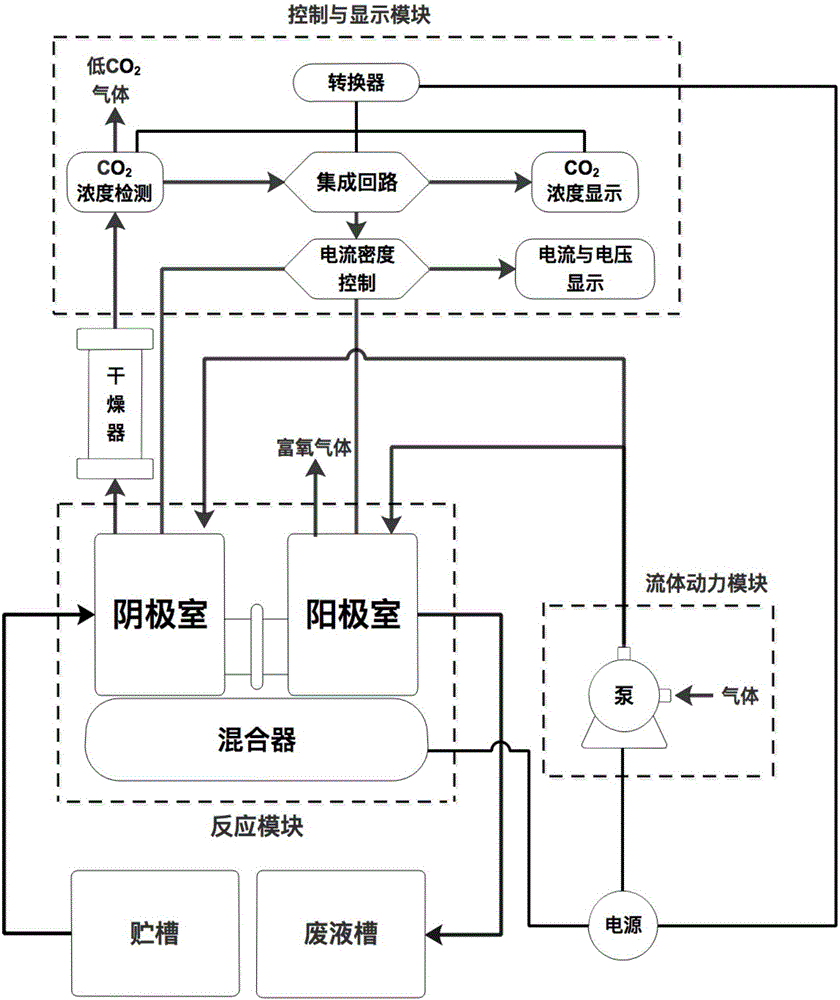
[0028] Example 1: CO 2 Electrochemical capture and storage system structure
[0029] figure 1 gives CO 2 Electrochemical capture and mineralization storage system structure. The system consists of three parts: fluid power module, reaction module and control and display module. The fluid power module is connected to the reaction module, which not only provides 2 The raw material gas can also be supplemented with supporting electrolytes and reactants. The control and display modules are connected to the reaction module and the fluid power module at the same time. On the one hand, the system controller provides power to the above-mentioned sensor devices, and controls the fluid power module to provide reactants and replenish electrolyte for the reactor according to the response of the sensor devices; on the other hand , There is a digital signal processor (DSP) in the controller to control the operation of the reactor, to provide the system with steady state, transient state...
Embodiment 2
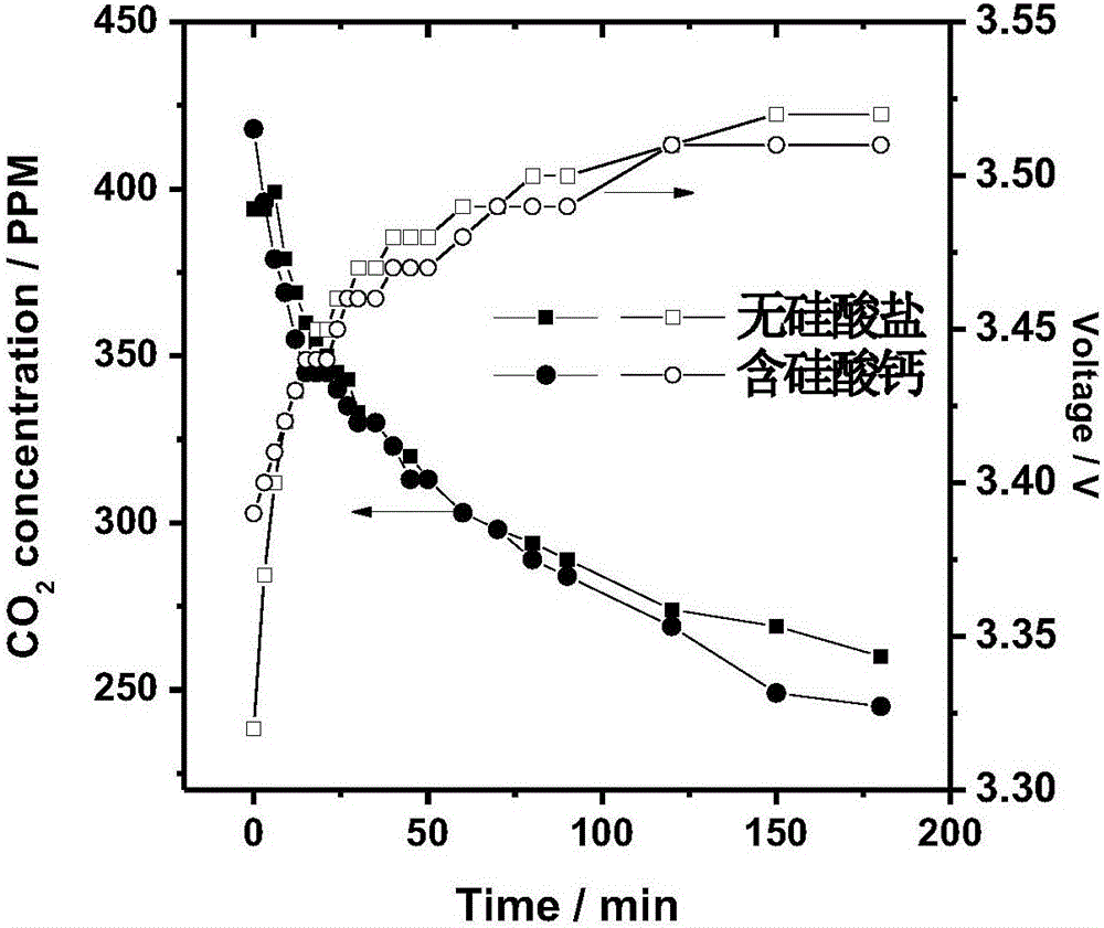
[0030] Example 2: CO 2 The structure of the electrochemical capture and mineralization storage system is the same as in Example 1. In this example, the addition of silicate is compared to the system CO 2 The absorption efficiency and the impact of emission products.
[0031] figure 2 .Given the electrochemical CO with and without silicate minerals 2 Capture and mineralization storage system, at a current density of 2mA·cm -2 Under the condition, the system’s response to CO in the air 2 Absorption effect and system tank pressure. It can be seen that the introduction of calcium silicate for CO 2 The absorption and system power consumption have obvious effects after 100 minutes, and the system containing calcium silicate exhausts gas CO 2 The concentration is relatively low. Table 1 shows the effect of the introduction of silicate on the pH of the discharge product after the system has been running for 8 hours. It can be seen that the introduction of calcium silicate sign...
Embodiment 3
[0034] Example 3: CO 2 The structure of the electrochemical capture and mineralization storage system is the same as in Example 1. In this example, the effect of silicate species on the system CO 2 influence on the absorption efficiency.
[0035] image 3 given in CO 2 After introducing calcium silicate, magnesium silicate, aluminum silicate and sodium silicate into the electrochemical capture and mineralization storage system, the CO 2 Comparison of absorption effects. During the operation of the system, the reaction module operates in a steady-state constant current mode, and its current is 2mA·cm -2 . It can be seen that the type of silicate affects the system CO 2 Transient and steady-state behavior of absorption. One hour after the system was started, the system of aluminum silicate and magnesium silicate was introduced to CO 2 Absorption is less effective than systems containing calcium silicate and sodium silicate. After 3 hours of operation, the system has ent...
PUM
 Abstract
Description
Claims
Application Information
 - R&D Engineer
- R&D Manager
- IP Professional
- Industry Leading Data Capabilities
- Powerful AI technology
- Patent DNA Extraction
Browse by: Latest US Patents, China's latest patents, Technical Efficacy Thesaurus, Application Domain, Technology Topic, Popular Technical Reports.
© 2024 PatSnap. All rights reserved.Legal|Privacy policy|Modern Slavery Act Transparency Statement|Sitemap|About US| Contact US: help@patsnap.com