A kind of ultra-low carbon steel rh refining furnace desulfurization method

An ultra-low carbon steel and refining furnace technology, applied in the field of iron and steel metallurgy, can solve the problems of unfavorable desulfurization reaction kinetic conditions, difficulty in further improving desulfurization effect, and slow melting speed of desulfurization agent, etc., to achieve convenient throwing, stable and efficient injection , the effect of prolonged residence time

Active Publication Date: 2019-04-23
SHANDONG IRON & STEEL CO LTD
View PDF3 Cites 0 Cited by
  • Summary
  • Abstract
  • Description
  • Claims
  • Application Information

AI Technical Summary

Problems solved by technology

For RH powder spraying desulfurization, the desulfurization rate is 70% to 90%, which can reduce the sulfur content in molten steel to 20×10 -6 Below, however, the RH powder spraying desulfurization process of the prior art will add various auxiliary equipment (specifically need to set up a top blowing spray gun or an additional submerged spray gun). These auxiliary equipment are complex in structure and difficult to maintain, which makes the desulfurization cost high. Not widely used
[0004] For desulfurization by the RH vacuum chamber input method, the desulfurization rate is 30% to 40%, and the sulfur content in molten steel can be less than 40×10 -6 , but in the desulfurization process of this process, there are the following deficiencies or constraints, which make it difficult to further improve the desulfurization effect:
[0005] (1) The desulfurization agent needs to reach a certain alkalinity to achieve the desulfurization effect, but the melting point of the desulfurization agent will increase after the alkalinity increases, which will slow down the melting speed of the desulfurization agent, which is not conducive to the kinetic conditions of the desulfurization reaction, so increase the alkalinity of the desulfurization agent and lowering the melting point of the desulfurizer are two contradictory aspects
[0006] (2) RH deep degassing and deep decarburization stage In order to achieve the purpose of reducing the amount of splashing and uniform degassing and decarburization, the height of the liquid steel level in the vacuum chamber is generally controlled at about 200mm, and the desulfurizer is put in from the silo at the top of the vacuum chamber Finally, because the liquid level of molten steel is low and the flow rate of molten steel in the vacuum chamber is fast, the desulfurizer is easily drawn into the ladle by the fast-flowing molten steel from the downcomer. slag contact, its desulfurization ability is inhibited, and the desulfurization rate is also reduced

Method used


Image

  • A kind of ultra-low carbon steel rh refining furnace desulfurization method
  • A kind of ultra-low carbon steel rh refining furnace desulfurization method

Examples


Embodiment 1

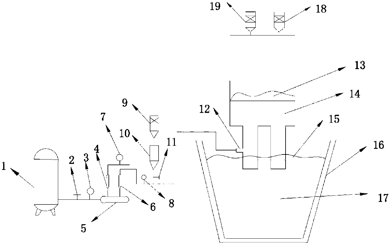
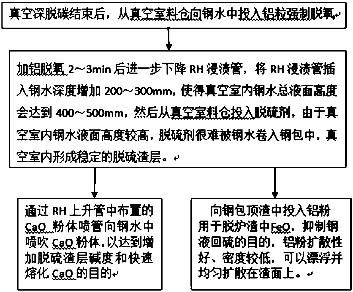
[0034] Such as figure 2 Shown, a kind of ultra-low carbon steel RH refining furnace desulfurization method, described method comprises the following steps:

[0035] 1) The production process of ultra-low carbon steel is formulated as follows: hot metal pretreatment desulfurization → LD (ladle) → slag retaining and tapping → ladle slag reformation → RH (vacuum refining) decarburization and desulfurization → continuous casting;

[0036] 2) The amount of molten steel in the converter is about 120 tons. During the process of putting steel into the converter, 400kg of granular lime is added along with the steel flow. After the steel is placed in the converter, 300kg of special modifier is evenly added to the slag surface / furnace (based on 800ppm of oxygen at the end of converter blowing, For every increase of 100ppm, add 30kg of modifier and 100kg of granular lime / furnace). After the converter is tapped, after the RH enters the station, the temperature is measured and the oxygen i...

Embodiment 2

[0047] Such as figure 2 Shown, a kind of ultra-low carbon steel RH refining furnace desulfurization method, described method comprises the following steps:

[0048] 1) The production process of ultra-low carbon steel is formulated as follows: hot metal pretreatment desulfurization → LD (ladle) → slag retaining and tapping → ladle slag reformation → RH (vacuum refining) decarburization and desulfurization → continuous casting;

[0049] 2) The amount of molten steel in the converter is about 120 tons. During the process of putting steel into the converter, 400kg of granular lime is added along with the steel flow. After the steel is placed in the converter, 300kg of special modifier is evenly added to the slag surface / furnace (based on 800ppm of oxygen at the end of converter blowing, For every increase of 100ppm, add 30kg of modifier and 100kg of granular lime / furnace). After the converter is tapped, after the RH enters the station, the temperature is measured and the oxygen i...


PUM

PropertyMeasurementUnit
particle sizeaaaaaaaaaa
particle diameteraaaaaaaaaa

Abstract

The invention discloses a desulphurization method for an ultra-low carbon steel RH refining furnace. The method comprises the following steps: 1) after the RH refining furnace arrives, measuring temperature and determining oxygen, determining whether blowing oxygen to raise the temperature and blowing oxygen for forced decarburization are required or not according to the temperature of the molten steel and the oxygen content of the molten steel, and then raising the temperature of the molten steel and deeply decarburizing the molten steel by formulating a corresponding process; 2) after vacuum deep decarburization, inputting aluminum particle into the molten steel from a vacuum chamber stock bin for forced deoxidization, further declining an RH dip pipe in 2-3min after adding aluminum to deoxidize, inserting the RH dip pipe into the molten steel to 200-300mm, and then inputting 2-5kg / ton steel of a desulfurizer from the vacuum chamber stock bin; 3) blowing CaO powder to the molten steel through a CaO power spray pipe of an RH ascending pipe while inputting the desulfurizer into the vacuum chamber stock bin; and 4) inputting 0.2-0.6kg / ton steel of aluminum powder into steel ladle top slag while inputting the aluminum particles into the molten steel from the vacuum chamber stock bin for forced deoxidization.

Description

technical field [0001] The invention belongs to the technical field of iron and steel metallurgy, in particular, the invention relates to a desulfurization method for an RH refining furnace suitable for ultra-low carbon steel. Background technique [0002] Among all kinds of refining equipment outside the furnace, RH vacuum refining has become one of the most important means of smelting high-quality steel. From the point of view of its refining function, in addition to the basic function of vacuum degassing, it can also be effectively used for decarburization and deoxygenation. In the production of low-carbon and ultra-low-carbon steel, weak deoxidation is used for tapping in the converter, and oxygen decarburization or carbon deoxidation is performed in the RH refining furnace. However, weakly deoxidized molten steel has a high content of dissolved oxygen in the steel and strong oxidizing properties of slag, so the slag basically has no desulfurization ability before the R...

Claims


Application Information

Patent Timeline
Patent Type & Authority Patents(China)
IPC IPC(8): C21C7/10C21C7/064C21C7/068
CPCC21C7/0037C21C7/064C21C7/068C21C7/10
Inventor 刘洪银郝帅孙建卫路峰袁鹏举倪培亮亓伟伟王奉县王孝科
Owner SHANDONG IRON & STEEL CO LTD
Why Eureka
Try Eureka