Nondestructive detection method and device for absorber absorption coefficient measurement and photoacoustic imaging simultaneously

An absorption coefficient, photoacoustic imaging technology, applied in diagnostic recording/measurement, medical science, diagnosis, etc., can solve problems such as inability to perform two-dimensional imaging

Pending Publication Date: 2017-05-31
JIMEI UNIV
View PDF3 Cites 11 Cited by
  • Summary
  • Abstract
  • Description
  • Claims
  • Application Information

AI Technical Summary

Problems solved by technology

Additional spectral information of the photoacoustic signal based on relative changes in different acoustic frequencies is also used to measure the optical absorption coefficient, but this method requires the use of two different wavelengths and ignores the influence of wavelength-dependent energy flux rates
A method of measuring the optical absorption coefficient of tissue combined with the light transmission model and using wavelet transform to correct the multi-frequency propagation attenuation of the photoacoustic signal. Due to the use of external light irradiation and forward acoustic detection, it is not suitable for living body detection, and cannot perform two-dimensional imaging

Method used


Image

  • Nondestructive detection method and device for absorber absorption coefficient measurement and photoacoustic imaging simultaneously
  • Nondestructive detection method and device for absorber absorption coefficient measurement and photoacoustic imaging simultaneously
  • Nondestructive detection method and device for absorber absorption coefficient measurement and photoacoustic imaging simultaneously

Examples


Embodiment Construction

[0051] The present invention will be further described below in conjunction with the accompanying drawings and embodiments.

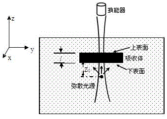
[0052] In this embodiment, the photoacoustic excitation and detection principle model of the method is as follows figure 2 shown. figure 2 The cuboid-shaped pure absorber is buried in a square scattering medium, the absorption coefficient of the pure absorber is a, the scattering coefficient is negligible, and the optical properties of the surrounding scattering medium are expressed by the scattering coefficient μ s , the absorption coefficient μ a , described by the anisotropy factor g. figure 2 Middle Z 0 Indicates the distance from the lower surface of the absorber to the surface of the diffuse light source, and l indicates the thickness of the absorber.

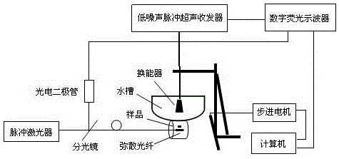
[0053] This embodiment provides a nondestructive testing device for absorber absorption coefficient measurement and simultaneous photoacoustic imaging, including a photoacoustic excitation l...


PUM


Abstract

The invention provides a nondestructive detection method and device for absorber absorption coefficient measurement and photoacoustic imaging simultaneously. The detection method comprises the steps that optical fibers are adopted to perform opto-acoustic excitation in a body through a tissue channel; upper and lower boundary opto-acoustic signals P1 and P2 and a time interval D of an absorber are obtained by utilizing a focusing-type ultrasonic transducer with a long focal region in a nondestructive mode; according to the absorption coefficient a of the absorber and the relation of opto-acoustic pressure amplitude ratio P2 / P1 of upper and lower boundaries of the absorber and thickness 1, the absorption coefficient a is inversed; an opto-acoustic image of the absorber is obtained while linear scanning of the transducer is combined. The detection device comprises an opto-acoustic excitation portion based on dispersing optical fibers, an electrical control mechanical scanning portion and an ultrasonic acquisition and processing portion based on the water-immersed focusing-type ultrasonic transducer with the long focal region. The detection method can achieve opto-acoustic excitation and opto-acoustic signal acquisition in a nondestructive mode, the influence of the energy flow rate relevant to wave length is overcome, result correction is not needed, and two-dimensional opto-acoustic imaging of the absorber can be performed simultaneously. The detection device is simple, easy, simple and convenient to operate and convenient to popularize clinically.

Description

technical field [0001] The invention relates to a medical photon diagnosis method and equipment, in particular to a non-destructive detection method and a device thereof for measuring the absorption coefficient of an absorber of a biological tissue and simultaneous photoacoustic imaging. Background technique [0002] The optical absorption coefficient of tissue is very important in reflecting the physiological state of tissue and in the determination of photodynamic therapy. Due to the strong scattering effect of tissue on light propagation, traditional tissue optics has not completely solved the non-destructive measurement of tissue optical absorption coefficient. Photoacoustic technology is based on the physical effect of photoinduced ultrasound, and detects photoacoustic signals to reflect the difference in light energy absorption of tissues. Therefore, the detected photoacoustic signals contain a large amount of optical absorption coefficient information of absorbers in ...

Claims


Application Information

Patent Timeline
IPC IPC(8): A61B5/00
CPCA61B5/0095A61B5/4381
Inventor 彭东青朱莉莉李志芳李晖叶高旭
Owner JIMEI UNIV
Why Eureka
Try Eureka