
Axial impeller and preparation method thereof

A technology of axial flow impeller and antioxidant, applied in the field of fan blades and its preparation, can solve the problems of increased vibration and noise, easy deformation, insufficient rigidity and high temperature resistance, etc., to reduce material deformation, increase material toughness, Effect of improving aging performance

Inactive Publication Date: 2017-05-10
武汉朗迪叶轮机械有限公司
View PDF7 Cites 1 Cited by
  • Summary
  • Abstract
  • Description
  • Claims
  • Application Information

AI Technical Summary

Problems solved by technology

[0003] Most of the existing axial flow impellers for air conditioners are made of ordinary glass fiber reinforced ABS, AS or PP materials. Due to their insufficient rigidity and high temperature resistance, they are prone to deformation during transportation and after long-term use, and vibration will occur during use. The problem of increased noise

Method used


Image

  • Axial impeller and preparation method thereof
  • Axial impeller and preparation method thereof
  • Axial impeller and preparation method thereof

Examples


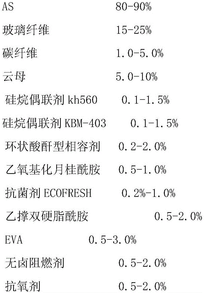
Embodiment 1

[0020] An axial flow impeller, which is injection molded from the following materials in terms of mass percentage:

[0021]

[0022] The preparation method of the above-mentioned axial flow impeller comprises the following steps: mixing AS resin, mica, silane coupling agent kh560, and silane coupling agent KBM-403 in a high mixer for 10-15min; Add glass fiber, carbon fiber and other additives to the main feeding port of the machine, melt and extrude, cool in a water tank, cut into pellets, and then dry and mix to obtain injection molding pellets; add injection molding pellets to injection molding Injection molding is carried out in a molding machine to obtain the axial flow impeller.

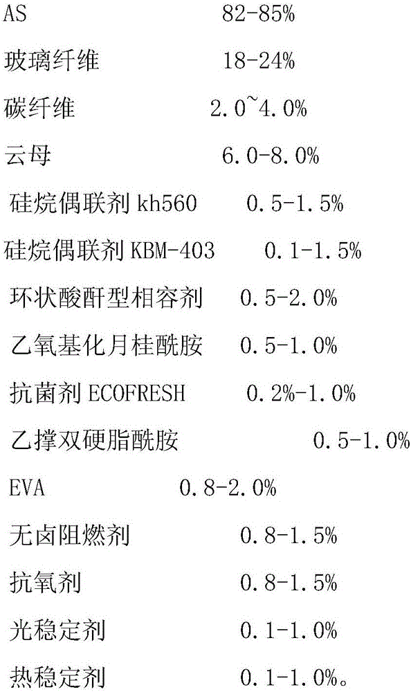
Embodiment 2

[0024] An axial flow impeller, which is injection molded from the following materials in terms of mass percentage:

[0025]

[0026] The preparation method of the above-mentioned axial flow impeller comprises the following steps: mixing AS resin, mica, silane coupling agent kh560, and silane coupling agent KBM-403 in a high mixer for 10-15min; Add glass fiber, carbon fiber and other additives to the main feeding port of the machine, melt and extrude, cool in a water tank, cut into pellets, and then dry and mix to obtain injection molding pellets; add injection molding pellets to injection molding Injection molding is carried out in a molding machine to obtain the axial flow impeller.

Embodiment 3

[0028] An axial flow impeller, which is injection molded from the following materials in terms of mass percentage:

[0029]

[0030]

[0031] The preparation method of the above-mentioned axial flow impeller comprises the following steps: mixing AS resin, mica, silane coupling agent kh560, and silane coupling agent KBM-403 in a high mixer for 10-15min; Add glass fiber, carbon fiber and other additives to the main feeding port of the machine, melt and extrude, cool in a water tank, cut into pellets, and then dry and mix to obtain injection molding pellets; add injection molding pellets to injection molding Injection molding is carried out in a molding machine to obtain the axial flow impeller.


PUM


Abstract

The invention relates to a fan blade and a preparation method thereof. An axial impeller is prepared from the following materials in percentage by mass through injection molding: 75 to 90 ppercent of AS (Acrylonitrile-Styrene), 15 to 20 percent of glass fiber, 1.0 to 5.0 percent of carbon fiber, 5.0 to 15 percent of mica, 0.1 to 1.5 percent of silane coupling agent kh 560, 0.1 to 1.5 percent of silane coupling agent KBM 403, 0.2 to 2.0 percent of cyclo-anhydride type compatilizer, 0.5 to 1.0 percent of ethoxylated lauramide, 0.2 to 1.0 percent of antibacterial agent ECOFRESH, 0.5 to 2.0 percent of microcrystalline paraffin, 0.5 to 3.0 percent of EVA (Ethylene-Vinyl Acetate), 0.5 to 2.0 percent of halogen-free flame retardant, 0.5 to 2.0 percent of antioxidant, 0.1 to 1.0 percent of light stabilizer and 0.1 to 1.0 percent of thermal stabilizer. The axial impeller disclosed by the invention has higher properties of heat resistance, chemical corrosion resistance, aging resistance, mildew resistance, ultraviolet radiation resistance and the like, the density is high, the hardness is high, the size deformation is small, and the tensile strength of a plastic material is increased.

Description

technical field [0001] The invention relates to wind blades and a preparation method thereof. Background technique [0002] With the improvement of living standards, people pay more and more attention to the requirements of the living environment. As an air conditioner used in an indoor airtight environment, its impact on fan noise is also increasingly concerned. The air conditioner indoor unit fan is the key component of the air supply of the air conditioner, so it has an important impact on the size of the indoor fan noise. [0003] Most of the existing axial flow impellers for air conditioners are made of ordinary glass fiber reinforced ABS, AS or PP materials. Due to their insufficient rigidity and high temperature resistance, they are prone to deformation during transportation and after long-term use, and vibration will occur during use. The problem of increased noise. Contents of the invention [0004] In order to solve the above-mentioned technical problems, the f...

Claims


Application Information

Patent Timeline
Patent Type & Authority Applications(China)
IPC IPC(8): C08L25/12C08L23/08C08K13/04C08K7/14C08K7/06C08K3/34C08K5/5435C08K5/20
CPCC08L25/12C08K2201/014C08L2201/02C08L2201/04C08L2201/08
Inventor 高文铭何书开
Owner 武汉朗迪叶轮机械有限公司
Learn More