
LED linear constant current soft start drive circuit

A drive circuit, linear constant current technology, applied in the field of LED constant current soft-start drive circuit, can solve the problems of LED load current impact, product cost rise, lamp reactive power soaring, etc., achieve large voltage fluctuation range, simple circuit design , The effect of simplifying the layout design

Active Publication Date: 2017-04-26
王汉忠
View PDF6 Cites 6 Cited by
  • Summary
  • Abstract
  • Description
  • Claims
  • Application Information

AI Technical Summary

Problems solved by technology

Although in the circuit design of LED lamps, the load voltage will be increased as much as possible to reduce the voltage difference, so as to reduce power consumption and improve efficiency. In areas where the power supply voltage is relatively stable, the application is no problem at all, but in areas where the power grid voltage fluctuates greatly When used in areas where the voltage rises above a certain level, the reactive power of the lamps will soar. In addition to the decrease in electrical efficiency, more importantly, it will affect the service life of the lamps.
[0004] The linear constant current drive belongs to the non-isolated topology. In the application field of LED lighting products, it basically works under the state of direct high-voltage drive of the mains. Based on the characteristics of the sine wave of the mains, after the mains voltage is rectified, its DC peak value The voltage is 1.414 times the input voltage, and there is a large voltage difference between the voltage of the LED load and the peak voltage of the power supply, so when the lamp is powered on, the current loaded on the LED load will generate a wave of more than 5 times the working current Surge pulses cause a large current impact on the LED load. Although the time is very short (about 100ms), this is a fatal flaw for the LED load. Frequent switching will greatly affect the life of the LED.
[0005] In order to solve the problem of current impact, a current method is to connect filter electrolytic capacitors in the power supply DC circuit, or connect electrolytic capacitors in parallel at both ends of the LED load, and use the power-on buffering characteristics of electrolytic capacitors to absorb the surge current. After adding electrolytic capacitors in the main circuit of the circuit, the power factor of the circuit will be greatly reduced. Generally, the power factor of a linear drive circuit without electrolytic capacitors is generally above 0.95, but after adding electrolytic capacitors, its power factor will be lower. will drop below 0.6
In addition, after the electrolytic capacitor is powered off, it takes a certain amount of time to release the internal electric energy. If the power is turned on again immediately after the power is turned off, or the switch shakes when the power is turned on for some reason, the above-mentioned buffering characteristics will be completely invalid, and , increasing the electrolytic capacitor will increase the cost of the product and increase the volume
Another current method is to connect a transient suppression diode TVS in parallel at both ends of the LED load. Although this can effectively suppress the power-on transient pulse, it cannot achieve soft start. In addition, due to the high cost of the transient suppression diode TVS, currently rarely used
[0006] In addition, currently some LED linear constant current drive circuits have an external dimming interface, which can be adjusted by PWM or linear level to realize the dimming function, but the circuit is complicated, and it needs to solve a single-chip dedicated regulated power supply, The cost is high, this method is generally only used in intelligently controlled lighting products

Method used


Image

  • LED linear constant current soft start drive circuit
  • LED linear constant current soft start drive circuit
  • LED linear constant current soft start drive circuit

Examples


Embodiment Construction

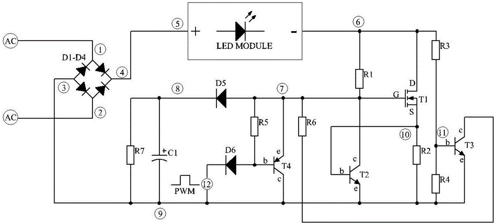
[0024] refer to Figure 1 to Figure 3 , a LED linear constant current soft-start drive circuit, comprising:

[0025] Working circuit: comprising field effect transistor T1, the drain D of said field effect transistor T1 is connected in series with the LED load (LED load between node 5 and node 6) and then connected to the DC power supply (the DC power supply is composed of rectifier diodes D1-D4 The anode (node ​​4) of the rectifier bridge constituted, for the convenience of description, the junction between the drain D of the field effect transistor T1 and the LED load is named node 6. The source S of the field effect transistor T1 is connected to the common ground (node ​​9) through the resistor R2, the gate G is connected to the node 6 through the resistor R1, and the junction between the resistor R1 and the gate G of the field effect transistor T1 is named as Node 7 , the junction between the resistor R2 and the source S of the field effect transistor T1 is named node 10 ...


PUM


Abstract

The invention discloses an LED linear constant current soft start drive circuit comprising a rectification circuit, a work loop circuit, a constant current control circuit, a voltage detection circuit, a soft start circuit and an external control circuit. Very simple circuit design is adopted for solving a complex technical problem. The LED linear constant current soft start drive circuit is advantaged by simple circuit, EMI-free property, high constant current precision, capability of tolerating a large voltage fluctuation range, and the like; a temperature compensation control function, a soft start function and an external light modulation function are fulfilled; intelligent control and wireless Internet of Things connection of LED lamps can be conveniently realized; comprehensive properties of a driver are improved while costs are lowered greatly; a special-purpose integrated LED drive chip can be made, layout design is simplified, manufacture costs of an integrated circuit are greatly lowered, and functions and performance reach a grade which can only be achieved via complex circuit design.

Description

technical field [0001] The invention relates to an LED driving circuit, in particular to an LED constant current soft start driving circuit. Background technique [0002] LED lighting has the advantages of energy saving and long service life and has entered thousands of households. In the prior art, there are many driving methods for LED lighting. Widely used, however, linear constant current drive also has some fatal shortcomings. [0003] Since the power device in the linear constant current drive is connected in series with the LED load, the power device works in a linear state, and the two ends of the power device need to withstand a certain voltage difference. The power generated by this voltage difference is reactive power and is driven by the linear constant current. The power device (usually MOSFET or other semiconductor power device) in the absorption, linear constant current is to control the current of the LED load by adjusting the voltage difference in the circu...

Claims


Application Information

Patent Timeline
Patent Type & Authority Applications(China)
IPC IPC(8): H05B33/08H05B44/00
CPCH05B45/395Y02B20/30
Inventor 王汉忠
Owner 王汉忠
Learn More