
Photolithographic method

A photolithography and photoresist technology, applied in the field of photolithography, can solve problems such as damage to metal wires

Inactive Publication Date: 2017-04-05
CSMC TECH FAB2 CO LTD
View PDF8 Cites 0 Cited by
  • Summary
  • Abstract
  • Description
  • Claims
  • Application Information

AI Technical Summary

Problems solved by technology

[0006] Based on this, it is necessary to provide a photolithography method for the problem that the metal wire is damaged due to excessive loss of resist when etching the metal wire.

Method used


Image

  • Photolithographic method
  • Photolithographic method

Examples


Embodiment Construction

[0021] In order to facilitate the understanding of the present invention, the present invention will be described more fully below with reference to the associated drawings. A preferred embodiment of the invention is shown in the drawings. However, the present invention can be embodied in many different forms and is not limited to the embodiments described herein. Rather, these embodiments are provided so that the disclosure of the present invention will be thorough and complete.

[0022] Unless otherwise defined, all technical and scientific terms used herein have the same meaning as commonly understood by one of ordinary skill in the technical field of the invention. The terms used herein in the description of the present invention are for the purpose of describing specific embodiments only, and are not intended to limit the present invention. As used herein, the term "and / or" includes any and all combinations of one or more of the associated listed items.

[0023] The st...


PUM

PropertyMeasurementUnit
thicknessaaaaaaaaaa

Abstract

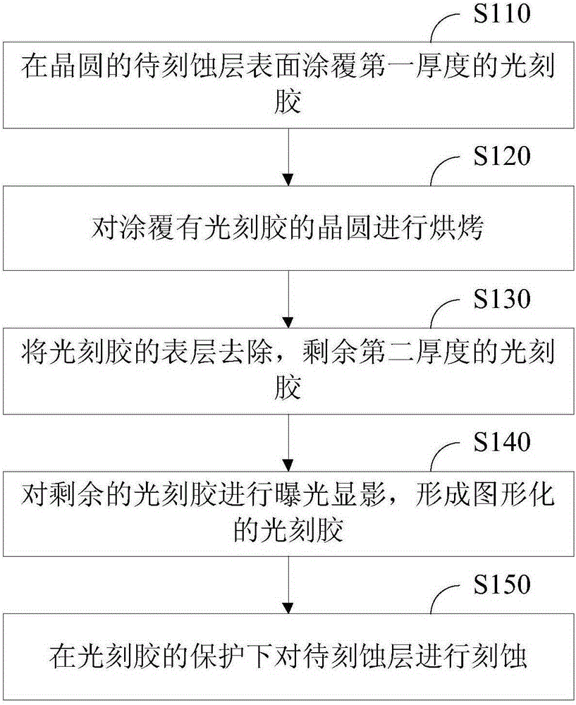
The invention relates to a photolithographic method. The photolithographic method comprises the following steps: coating the surface of a to-be-etched layer of wafer with a photoresist having first thickness; baking the wafer coated with the photoresist; removing the surface layer of the photoresist after baking to obtain the photoresist having second thickness; performing exposure and development on the residual photoresist to form graphical photoresist; and etching the to-be-etched layer under protection of the graphical photoresist. The organic molecules in the photoresist are fully bound, the anti-etching capability is increased, the photoresist is compact and uniform, and has stronger anti-etching capability, residual amount of the photoresist after etching is effectively increased, damage of an etching step on the to-be-etched layer is avoided, and electricity performance and yield rate stability of the equipment are increased.

Description

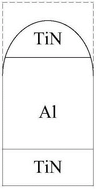
technical field [0001] The invention relates to semiconductor manufacturing technology, in particular to a photolithography method. Background technique [0002] In the chip manufacturing process, after the MOS (metal oxide semiconductor) tube is formed, it will enter the manufacturing process of metal wires. For the 8-inch wafer 0.13 micron process, most of them use AL (aluminum) as the metal wire. The manufacturing process of metal wires includes several key steps such as Al deposition, photolithography, and etching. [0003] In a conventional process, the metal wire structure includes a bottom layer Ti / TiN (ie titanium or titanium nitride, the same below), a main body Al and a surface layer Ti / TiN. The thickness of the first layer of metal (Metal 1) AL is 3000 angstroms. The etching step of the first layer of metal needs to etch off the metal film in a specific area, and etch off the silicon dioxide below the area to a certain thickness (that is, to ensure a certain ox...

Claims


Application Information

Patent Timeline
Patent Type & Authority Applications(China)
IPC IPC(8): G03F7/20
Inventor 李健胡骏
Owner CSMC TECH FAB2 CO LTD
Learn More