
A plate heat exchanger with an insert support

A plate heat exchanger and plate heat exchange technology, applied in indirect heat exchangers, heat exchanger types, heat exchanger shells, etc., can solve the problems of high gas flow resistance, large welding range, and weak ability to withstand pressure differences , to achieve the effect of improving sealing reliability, convenient cleaning and maintenance, and large sealing range

Active Publication Date: 2019-05-24
EAST CHINA UNIV OF SCI & TECH
View PDF9 Cites 0 Cited by
  • Summary
  • Abstract
  • Description
  • Claims
  • Application Information

AI Technical Summary

Problems solved by technology

[0003] 1. It is difficult to withstand high pressure and high pressure difference. Limited by the pressure resistance of the sealing gasket, the working pressure of the detachable plate heat exchanger is generally not higher than 2.0MPa. The fully welded plate developed by Finland VAHTERUS and China Gansu Lanke Petrochemical, etc. A plate-and-shell heat exchanger is formed in a cylindrical shell, and the pressure resistance can reach 8.0MPa, but the welding range is large, and at the same time it loses the advantages of easy cleaning and maintenance, and the application field is limited.
[0004] 2. Sensitive to dirt. Since the peak contact of adjacent plates forms a support and the distance between the plates is small, scaling will easily increase the flow resistance or block the flow channel, resulting in a decrease in heat transfer efficiency or frequent disassembly and cleaning, so it is not applicable Liquids with solid particles or fibers (such as sewage, flue gas) or solutions that are prone to crystallization during heat exchange
[0005] 3. Not suitable for high flow rate occasions (such as gas heat exchange)
Because the flow channel is too narrow and the gas flow resistance is high, the plate heat exchanger is rarely used in gas heat exchange (such as flue gas waste heat recovery, compressor inter-stage cooler) and other occasions.
[0006] 4. Not suitable for surface evaporation occasions (such as evaporative condensers)
The convex points pressed by the plate are used as support, the fluid is not easy to distribute evenly in the wedge-shaped flow channel, and the ability to withstand the pressure difference is weak

Method used


Image

  • A plate heat exchanger with an insert support
  • A plate heat exchanger with an insert support
  • A plate heat exchanger with an insert support

Examples


Embodiment 1

[0080] 1. Structure:

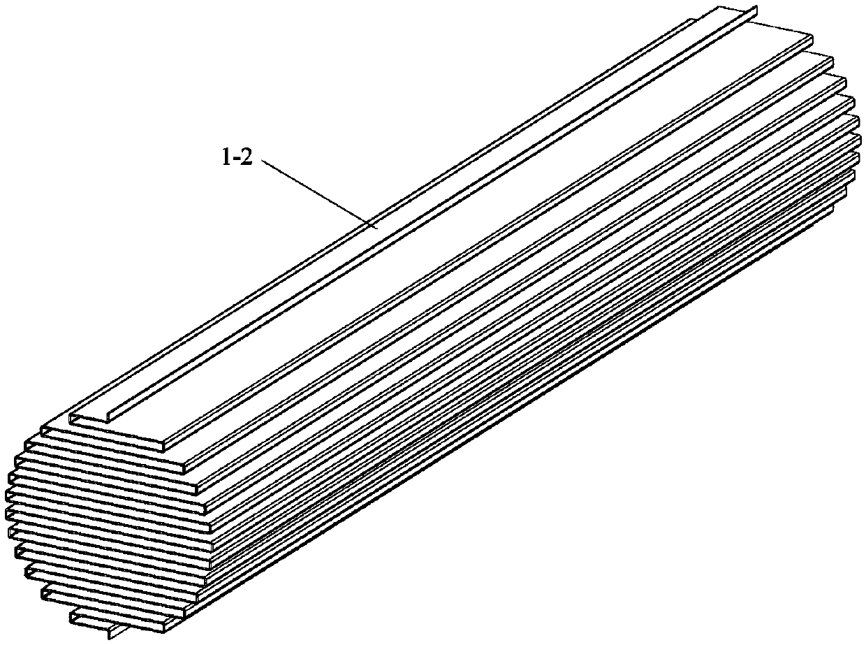
[0081] Such as Figure 7 , 23 As shown, a plate heat exchanger includes a B plate heat exchange unit 1-2, a continuous twisted strip plate 3-1, a double semicircular shell 4-3, a head 6, and an integrated isolation grid without a sealing ring 9- 2 and side interface 7. The continuous twisted belt plate 3-1 is arranged between the plates of the B plate heat exchange unit 1-2, and the double semicircular shell 4-3 is wrapped in the B plate through the connection of the shell straight edge 11-1 and the sealing edge 11-2. Outside the plate heat exchange unit 1-2, the head 6 is arranged at both ends of the double semicircular shell 4-3 through the connection of the head flange 10-2 and the shell flange 10-1, an integral type without a sealing ring The isolation grid 9-2 is set between the head 6 and the double semicircle shell 4-3, the side interface 7 is connected to the side opening of the double semicircle shell 4-3, and can be connected with other pipe...

Embodiment 2

[0113] According to the relevant drawings, a plate heat exchanger includes A plate heat exchange unit 1-1, discontinuous twisted belt plate 3-2, rectangular flat shell 4-2, head 6, separated strip isolation grid 9-1 and the side interface 7 . Such as Figure 22 As shown, the seal head 6 is arranged at both ends of the rectangular flat shell 4-2, the side interface 7 is set on the wall of the rectangular flat shell 4-2 and is adjacent to the seal head 6, and the rectangular flat shell 4-2 is provided with bolts Hole 8. in:

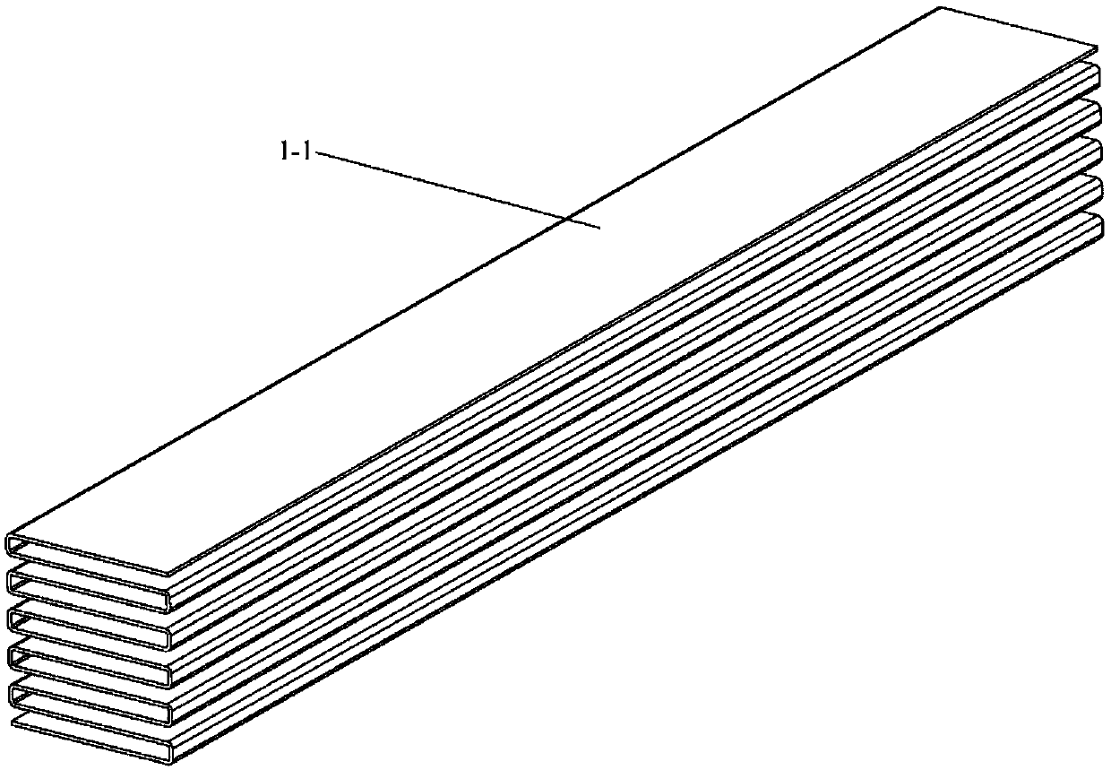
[0114] (1) Plate heat exchange unit: such as figure 1 As shown, the A plate heat exchange unit 1-1 is a plate heat exchange unit with a rectangular cross-section formed by reciprocating folding of a whole metal flat plate.

[0115] (2) Supports between boards: such as Figure 5 , 8 , 9, the support between the plates is a discontinuous twisted belt plate 3-2: it is made of helical twisted belts 2-1 that are parallel to each other and have a certain di...

Embodiment 3

[0122] According to the relevant drawings, a plate heat exchanger includes a plate heat exchange unit 1-1, a diamond-shaped twisted belt plate 3-3, an integrated shell 4-1, a head 6, and a separate strip isolation grid 9-1 and side interface 7, wherein:

[0123] (1) Supports between boards: such as Figure 10 , 11 As shown in 12, the support between the plates is a diamond-shaped twisted belt plate 3-3: it is formed by connecting the spiral twisted belts 2-1 arranged crosswise and having a certain angle between the axial direction and the fluid flow direction with the groove 2-2. Its characteristic is that its supporting strength and turbulence effect are weaker than those of the discontinuously twisted belt plate 3-2, but the flow resistance is smaller.

[0124] (2) Shell: Since the difference between the pressure in the flow channel and the ambient pressure is below 10kPa, an integrated shell 4-1 can be used, such as Figure 18 , 19 As shown, the metal plate forming A pl...


PUM


Abstract

The invention relates to a plate heat exchanger provided with internally-inserted supports. The plate heat exchanger comprises a plate heat exchange unit, the intra-plate supports, a shell, seal plugs, separation fences and side connectors. The plate heat exchange unit is composed of a plurality of parallel plates partitioning the space in the shell into two runners, wherein the two runners do not communicate. Different from existing corrugated plates, the plates are supported by the intra-plate supports instead of making direct contact with one another, and the pressure on the two sides of each plate is balanced. The intra-plate supports are integral plates of spiral twisted band structures, are arranged between the plates, and are preferably arranged on the sides, with the lower pressure, of the plates, or the two sides of the plates. The spiral twisted band structures interfere with fluid to facilitate heat transfer. The plate heat exchanger provided with the internally-inserted supports has the advantages that high pressure and high pressure differences are borne, the reliability is improved, cleaning and maintenance are convenient, and the manufacturing cost is lowered.

Description

technical field [0001] The invention relates to industrial heat exchange equipment, in particular to a plate heat exchanger. Background technique [0002] Since the plate heat exchanger came out in 1878, it has developed rapidly in recent decades and has been widely used in various industries such as food, pharmaceuticals, chemicals, metallurgy, and electric power. Plate heat exchangers usually stack metal sheets with odd and even plates with opposite corrugation directions, and press them at both ends to form heat exchange channels. Compared with the traditional shell-and-tube heat exchanger, the plate heat exchanger has the advantages of compact structure, large average temperature difference of heat transfer, high heat transfer efficiency at low flow rate, convenient installation and maintenance, etc., especially suitable for the recovery of low-grade heat energy, high Viscous fluid heat transfer. But there are also the following problems: [0003] 1. It is difficult t...

Claims


Application Information

Patent Timeline
Patent Type & Authority Patents(China)
IPC IPC(8): F28D9/00F28F3/02F28F9/007F28F11/02
CPCF28D9/0081F28F3/025F28F9/0075F28F11/02F28F2225/04
Inventor 曾力丁轩福贞涂善东
Owner EAST CHINA UNIV OF SCI & TECH
Learn More