
Double-motor brake actuation mechanism of vehicle decoupling distribution brake system

A braking system and actuator technology, applied in the direction of brake actuator, brake type, gear shifting mechanism, etc., can solve the problem of inability to shunt, and achieve the effect of preventing excessive temperature, compact structure, and good resistance to failure.

Active Publication Date: 2017-03-22
JIANGSU UNIV OF TECH
View PDF9 Cites 11 Cited by
  • Summary
  • Abstract
  • Description
  • Claims
  • Application Information

AI Technical Summary

Problems solved by technology

However, most of the current EMB systems are single-motor actuators, which fail to make full use of the vehicle's braking energy to drive the friction brake, and cannot share the vehicle's braking load to reduce the wear of the friction brake pair.
So far, there has been little mention of dual-motor brake actuators in automotive decoupling distributed braking systems

Method used


Image

  • Double-motor brake actuation mechanism of vehicle decoupling distribution brake system
  • Double-motor brake actuation mechanism of vehicle decoupling distribution brake system
  • Double-motor brake actuation mechanism of vehicle decoupling distribution brake system

Examples


Embodiment 1

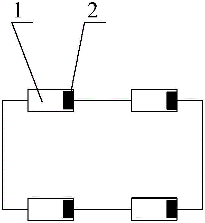
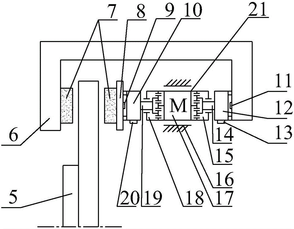
[0026] Such as figure 1 As shown, each wheel 1 is independently provided with a brake actuator 2, wherein the brake actuator 2 is a dual-motor brake actuator of the automobile decoupling distributed braking system, such as figure 2 As shown, it includes a brake disc 5, a brake execution part 3 and a regenerative motor part 4, such as image 3As shown, the brake executive part 3 includes a stepper motor 17 and a brake caliper body 6, the two ends of the brake caliper body 6 are respectively located on both sides of the brake disc 5, and the stepper motor 17 is arranged between the brake caliper body 6 and the brake disc 5, and the brake caliper body 6 and the stepper motor 17 are both slidably connected with the housing 16 of the brake execution part, and the brake caliper One end of the body 6 is provided with a friction block 7, and the other end is connected with the stepping motor 17;

[0027] Such as image 3 As shown, the stepper motor 17 has two output shafts, wherei...

Embodiment 2

[0037] The difference from Example 1 is that, as Figure 5 As shown, the stepper motor 17 has only one output shaft, and saves the second planetary wheel, the second leading screw 14, the second nut 12, the second limit switch 11 and the second displacement sensor 13 connected with it, and the stepping One end of the motor 17 is directly fixedly connected with one end of the brake caliper body 6 . Compared with Embodiment 1, the volume of the brake actuator 2 is reduced, and the basic function and basic working principle of each component are similar to Embodiment 1.


PUM


Abstract

The invention relates to the technical field of vehicle brake, in particular to a double-motor brake actuation mechanism of a vehicle decoupling distribution brake system. The mechanism comprises a brake disc, a brake actuation part and a regeneration motor part; the brake actuation part includes a stepper motor and a brake clamp body; two ends of the brake clamp body are respectively positioned on two sides of the brake disc; the brake clamp body and the stepper motor are both slidingly connected with a shell of the brake actuation part; a friction block is arranged at one end of the brake clamp body; the other end of the brake clamp body is connected with the stepper motor; the stepper motor is in transmission connection with a first lead screw; a first nut is arranged on the first lead screw, and is connected with the friction block; the friction block on the brake clamp body and a friction block on a first nut are positioned on two sides of the brake disc; the regeneration motor part includes an electromagnetic clutch, a regeneration motor, a battery set and an electronic control unit; the battery set is electrically connected with the stepper motor; and the electronic control unit controls connection and disconnection of current between the battery set and the stepper motor. The mechanism converts brake energy to electric energy as brake power, and can share brake loads.

Description

technical field [0001] The invention relates to the technical field of vehicle braking, in particular to a dual-motor braking actuator of an automobile decoupling distributed braking system. Background technique [0002] The braking system is one of the important components of the automobile chassis, which is directly related to the comprehensive performance of the automobile and the safety of life and property. Although the traditional hydraulic and pneumatic braking systems can meet the requirements of the existing braking regulations, there are complex pipeline arrangements, relying on vacuum booster devices, slow braking response speed, non-active adjustment of braking torque, and difficulty in matching Other deficiencies such as system integration control are not suitable for the development requirements of automobiles, especially electric vehicle chassis integration control. [0003] The electronically controlled braking system realizes the decoupling of the braking s...

Claims


Application Information

Patent Timeline
Patent Type & Authority Applications(China)
IPC IPC(8): F16D55/22F16D65/14F16D66/02F16D65/847F16D121/24
CPCF16D55/22F16D65/14F16D65/847F16D66/02F16D2121/24
Inventor 王奎洋邵超超赖晓杰王忠收童欣卞军军姜庆歧唐金花
Owner JIANGSU UNIV OF TECH
Learn More