
Visual choline sensor based on bipolar electrode array

A bipolar electrode and sensor technology, applied in the field of biosensors, can solve the problems of limited clinical detection application, narrow linear range, short service life, etc., and achieve the effect of promoting electron transfer, low cost, and reducing detection cost.

Inactive Publication Date: 2017-03-08
CHINA PHARM UNIV
View PDF5 Cites 5 Cited by
  • Summary
  • Abstract
  • Description
  • Claims
  • Application Information

AI Technical Summary

Problems solved by technology

The use of enzymes can ensure the selectivity of the sensor, but the immobilization method of the enzyme and its activity are still a problem that needs to be further studied
In addition, the introduction of intermediaries can greatly improve the performance of the sensor, but it also introduces complexity and limitations
At present, biosensors for the detection of choline concentration in human serum have been reported, but due to the shortcomings of poor anti-interference, narrow linear range, and short service life, they are limited in clinical detection applications.

Method used


Image

  • Visual choline sensor based on bipolar electrode array
  • Visual choline sensor based on bipolar electrode array
  • Visual choline sensor based on bipolar electrode array

Examples


Embodiment 1

[0054] Example 1 Preparation of Visual Choline Sensor Based on Bipolar Electrode Array

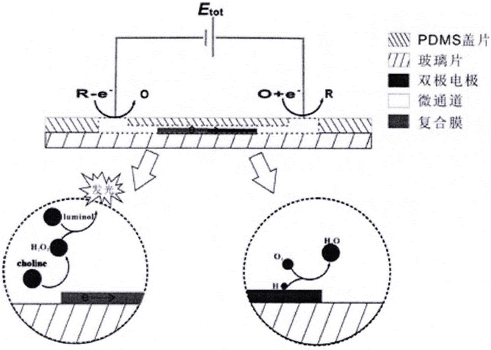
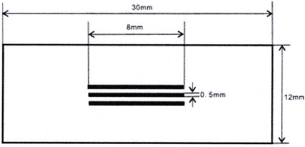
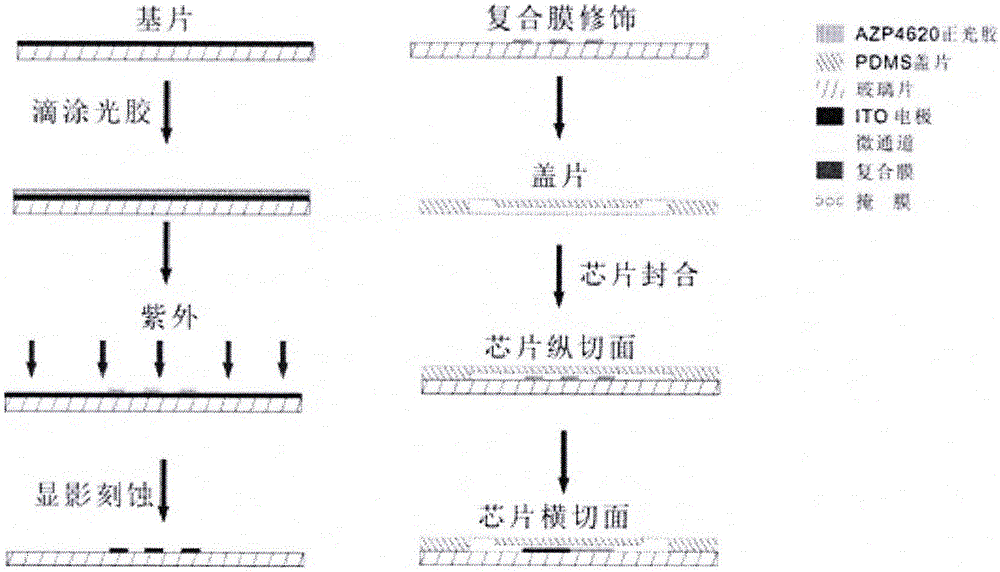
[0055] Such as figure 1 , figure 2 , image 3 Shown, a kind of preparation method of the visualization choline sensor based on bipolar electrode array, comprises steps:

[0056] 1) Preparation of coverslips

[0057] Mix the PDMS monomer and the curing agent at a mass ratio of 8:1-12:1 and stir evenly to obtain the PDMS mother liquor. Place the PDMS mother liquor at 4°C for 5-20 minutes, then degas for 2040 minutes; after degassing, pour it into silane Equilibrate above the silanized PDMS positive mold for 5-15 minutes, then cover with plastic wrap, heat and cure at 70-80°C for 1-2 hours; after curing, peel the PDMS from the silanized PDMS positive mold and cut it into 3.0cm*1.2cm The cover slip contains a channel groove; use a 14G flat needle to process a circular hole with a diameter of 0.5 cm at each end of the PDMS cover slip channel for sample injection and placement of driving el...

Embodiment 2

[0069] Example 2 The visual choline sensor based on the bipolar electrode array is used for the detection of choline

[0070] The method of detecting choline with a visual choline sensor based on a bipolar electrode array is used, and a platinum wire is placed on the holes at both ends of the cover sheet as the driving electrode; the driving electrode provides a driving voltage of 8V through a DC regulated power supply; Inject 20 microliters of buffer solution containing choline solution to be tested and luminol into the groove, wherein the concentration of PBS is 0.01mol / L, the pH is 7.4, the concentration of choline is 0.02mM-5mM, and the concentration of luminol The concentration is 1.3mmol / L; choline oxidase modified on the surface of the bipolar electrode catalyzes the reaction of dissolved oxygen and choline to generate H 2 o 2 , and under the drive of an applied voltage, electrochemiluminescence occurs with luminol, and the generated electrochemiluminescence signal is ...


PUM


Abstract

The invention discloses a visual choline sensor based on a bipolar electrode array and belongs to the technical field of biosensors. The visual choline sensor realize visual detection of choline by using electrochemiluminescence imaging on the basis of choline oxidase / carbon nanotube / chitosan modified electrode, bipolar electrode and micro-fluidic chip technologies. A bipolar electrode is a conducting material capable of having an electrochemical reaction at the tail end without external electrical contact, so that a large quantity of array analysis can be facilitated, and mass production is facilitated, and the detection cost is reduced. The adopted electrochemiluminescence imaging technology has the advantages of high sensitivity, simple optical path and the like and is applied to visual detection of choline, the method is convenient, and the result is direct.

Description

technical field [0001] The invention relates to the technical field of biosensors, in particular to a method for detecting choline with a visual choline sensor based on a bipolar electrode array. Background technique [0002] Choline is an organic base that is a precursor of acetylcholine and a constituent of lecithin, also present in sphingomyelin. Choline plays an important role in adjusting fat metabolism in animals, controlling cholesterol accumulation, preventing fatty liver, ensuring normal life activities of somatic cells, promoting cartilage development and normal operation of nervous system, etc. Its detection has important biological significance. significance. [0003] Since choline has no ultraviolet absorption and electrochemical activity, the catalytic reaction of enzymes has become an important method for the determination of choline. Most choline sensors use peroxidase, with the help of electronic mediators or nanomaterials. The use of enzymes can ensure t...

Claims


Application Information

Patent Timeline
IPC IPC(8): G01N21/76G01N27/30G01N27/327
CPCG01N21/76G01N27/305G01N27/3278
Inventor 许林茹齐炼文肖依吕志敏
Owner CHINA PHARM UNIV
Learn More