
Automatic double-head tube end forming machine

A double-head pipe and forming machine technology, applied in the direction of feeding device, manufacturing tool, positioning device, etc., can solve the problems of pipe clamp positioning influence, affecting pipe forming accuracy, etc., to improve stability, prevent material jamming, and scientific structure reasonable effect

Active Publication Date: 2018-09-25
GUANGZHOU LIQI METAL PROD
View PDF1 Cites 0 Cited by
  • Summary
  • Abstract
  • Description
  • Claims
  • Application Information

AI Technical Summary

Problems solved by technology

[0004] The double-head special-shaped shrinking tube forming machine with the above structure has the following disadvantages: the tube clamp needs to be moved multiple times during the entire processing process, and the flatness of the fuselage, the screw rod and the platform for placing the equipment, etc., will affect the movement of the tube clamp. Positioning has a large or small impact, which affects the forming accuracy of the pipe

Method used


Image

  • Automatic double-head tube end forming machine
  • Automatic double-head tube end forming machine
  • Automatic double-head tube end forming machine

Examples


Embodiment 1

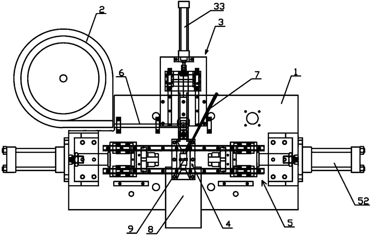
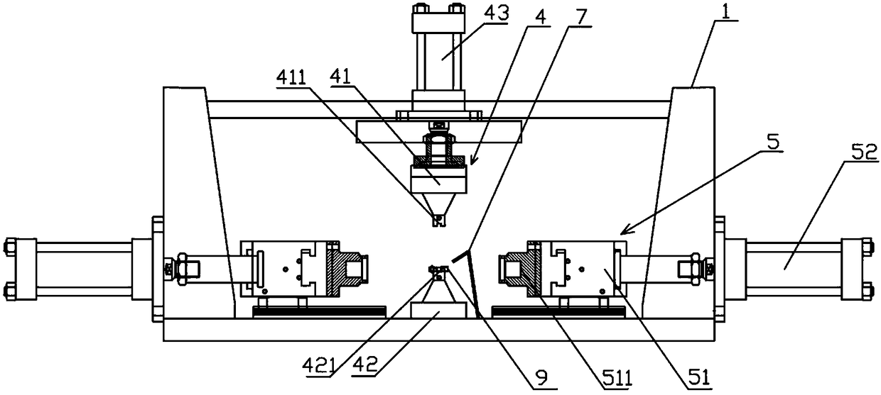
[0026] Embodiment 1: an automatic double-head pipe end forming machine, comprising a body 1, a vibration plate 2, a feeding device 3, a clamping device 4 and a forming device 5, the vibration plate 2 is fixed on the body 1, and the vibration The disc 2 communicates with the feeding device 3 through the feed pipe 6;

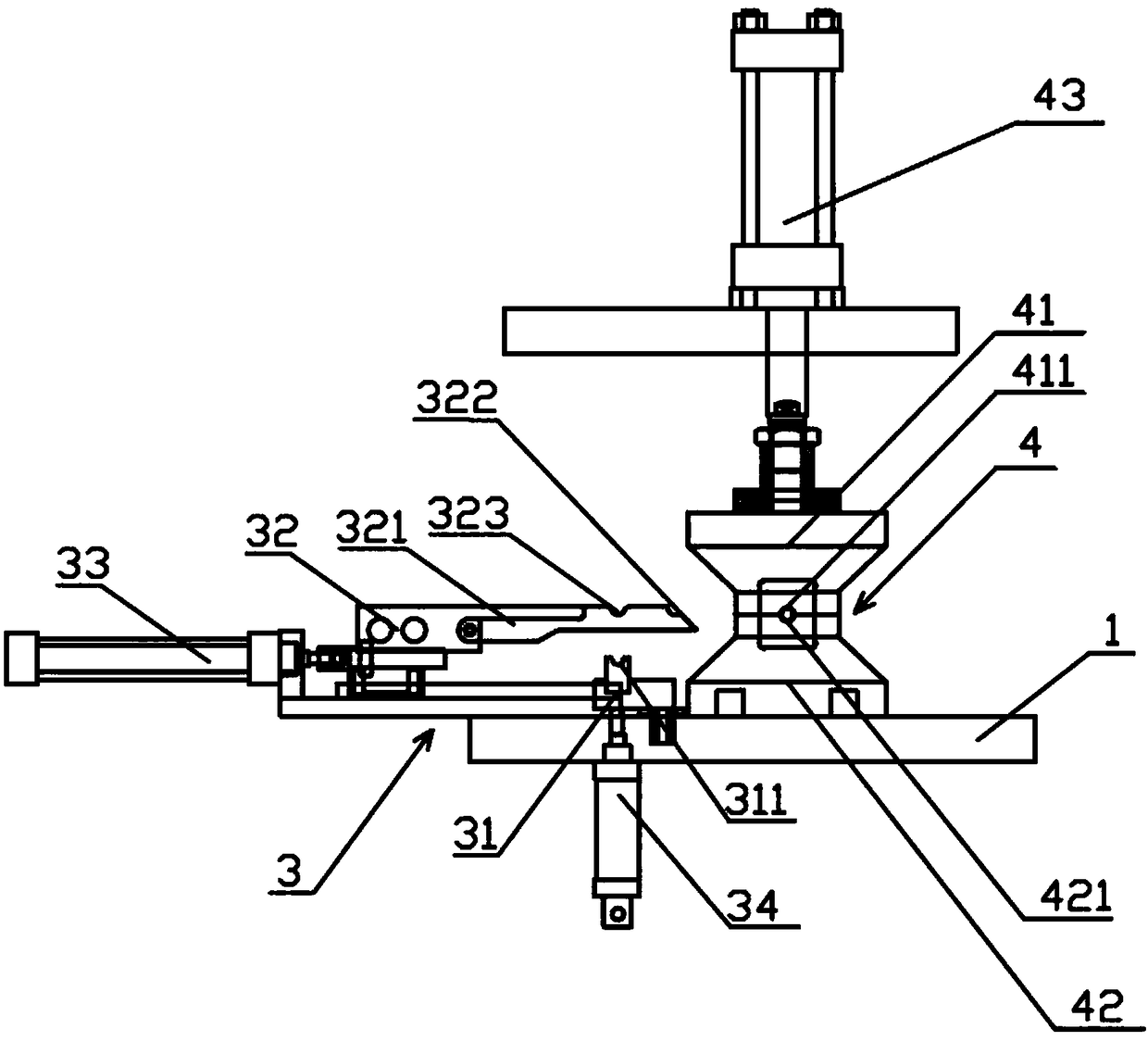
[0027] The feeding device 3 includes a push seat 31, a push arm 32, a first drive device 33 and a fourth drive device 34, the first drive device 33 is fixedly connected to the fuselage 1, and the push arm 32 is connected to the first drive device 33 connection, the push arm 32 is provided with two parallel push rods 321, the head of each push rod is provided with an inclined rod head 322, and the middle part of each push rod 321 is provided with a first material seat 323, and the push rod 321 is provided with a first material seat 323. The upper end of the seat 31 is provided with a second material seat 311, the second material seat material 311 is connected to tw...

Embodiment 2

[0032] Embodiment 2: The difference from Embodiment 1 is that the forming part 51 includes a fixed part 53, a rotating part 54 and a servo motor 55, the fixed part 53 is fixedly connected to the servo motor 55, and the rotating part 54 is connected to the servo motor 55. The rotating shaft 551 of the servo motor 55 is connected, and the rotating part 54 is provided with two molding dies 511 (the number of molding dies in this embodiment is two, but not limited to two, it can be more than two); working principle and embodiment 1 is that the servo motor 55 can control the rotation of the rotating part 54, and rotate and replace the forming mold 511 as required.


PUM


Abstract

The invention relates to an automatic double-end pipe end forming machine. The automatic double-end pipe end forming machine comprises a machine body, a vibration plate, a feeding device, a clamping device and a forming device. The vibration plate communicates with the feeding device through a feeding pipe. The feeding device comprises a pushing base, a pushing arm and a first driving device. The pushing arm is connected with the first driving device and provided with two parallel push rods. An oblique rod head is arranged at the head of each push rod. A first material base is arranged in the middle of each push rod. A second material base is arranged at the upper end of the pushing base and connected with the two first material bases. The clamping device comprises an upper clamping part, a lower clamping part and a second driving device. The upper clamping part is connected with the second driving device. A lower clamping port is formed in the top of the lower clamping part. An upper clamping port is formed in the bottom of the upper clamping part. The forming device comprises a pair of forming components located on the two sides of the clamping device and a pair of third driving devices connected with the forming components correspondingly. Each forming component comprises at least one forming mold.

Description

technical field [0001] The invention relates to the field of pipe material processing equipment, in particular to an automatic double-head pipe end forming machine. Background technique [0002] The current pipe processing mainly includes processes such as pipe expansion, pipe shrinkage, chamfering and pressing. The double-head pipe end forming machine is a kind of equipment that can simultaneously form and process the two ends of pipe workpieces. It is suitable for pipe insertion, Forming and processing of pipes of various shapes at the connection parts of automobile oil pipes, air pipes, water pipes, and air-conditioning pipes. The existing patent application number is 201620230480.5, a fully automatic double-head special-shaped shrinking tube forming machine, including a frame. The frame is equipped with a driving device, a pipe clamp and a pipe delivery mechanism. The pipe delivery mechanism is located in Below the pipe clamp, the pipe conveying mechanism includes a con...

Claims


Application Information

Patent Timeline
Patent Type & Authority Patents(China)
IPC IPC(8): B21D41/00B21D43/02B21D43/00B21D41/02B21D41/04
CPCB21D41/00B21D41/02B21D41/04B21D43/003B21D43/006
Inventor 覃耀吴郁青沙瑞香
Owner GUANGZHOU LIQI METAL PROD
Learn More