Antenna protection limiter structure

A technology of antenna protection and limiter, which is applied in the field of antenna protection limiter structure, can solve the problems of affecting recirculation, difficult to meet, easy sublimation of graphite materials, etc., and achieve the effect of solving recirculation and tritium retention

Inactive Publication Date: 2017-02-01
INST OF PLASMA PHYSICS CHINESE ACAD OF SCI
View PDF10 Cites 5 Cited by
  • Summary
  • Abstract
  • Description
  • Claims
  • Application Information

AI Technical Summary

Problems solved by technology

However, graphite materials are prone to sublimation, are not resistant to chemical corrosion, and tritium retention caused by redeposition affects recycling, making it difficult to meet the requirements of the first wall material of future nuclear fusion devices
The remaining traditional first wall materials such as tungsten, beryllium and molybdenum also have their own insurmountable shortcomings

Method used


Image

  • Antenna protection limiter structure
  • Antenna protection limiter structure
  • Antenna protection limiter structure

Examples


Embodiment Construction

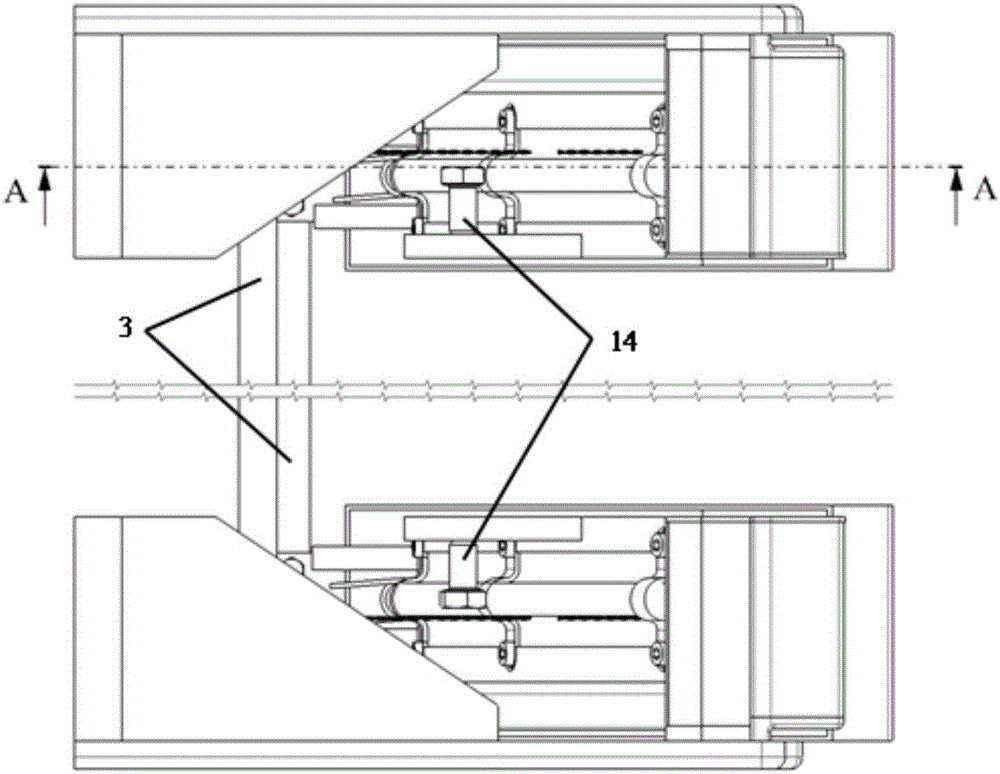
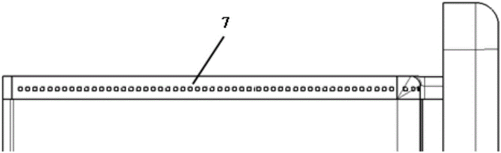
[0022] See attached Figure 1-4 , an antenna protection limiter structure, including a protection limiter guide plate 1, a heat sink structure 2, an electromagnetic pump electrode 3, a recovery box 4, a lithium flow pipeline 5, a distribution box 6, a micro flow channel 7, and a heating plate 8 , Cooling medium inlet and outlet pipe 9, heat sink cooling channel 10, thermocouple 11, heating wire 12, screw 13, screw 14, side protection plate 15. The recovery box 4 is provided with liquid lithium, the lithium flow pipeline 5 is connected between the recovery box 4 and the distribution box 6, the electromagnetic pump electrode 3 is connected with the liquid lithium in the recovery box 4, the micro channel 7 is connected with the distribution box 6, and the micro flow channel 7 is connected with the distribution box 6. Each liquid outlet on the flow channel 7 is facing the surface of the deflector 1 of the protective limiter; by controlling the positive and negative poles of the el...


PUM


Abstract

The invention discloses an antenna protection limiter structure. The antenna protection limiter structure comprises a protection limiter guide plate, a heat sink structure, an electromagnetic pump electrode, a recovery box, a lithium flow pipeline, a distribution box, a heating plate, a cooling medium in and out pipe, a heat sink cooling channel, a temperature measurement thermocouple, a heating wire, a connection screw and a side protection plate. According to the antenna protection limiter structure, quite high heat load in a vacuum chamber can be borne, the antenna main body structure can be prevented from being directly attached by high-energy particles in the vacuum chamber, a first wall material and plasma are prevented from mutually interacting to damage the operation environment of the vacuum chamber; re-circulation and tritium retention problems of deposition particles of a first wall can be effectively solved on the basis of circulation flow and renewable property of the liquid lithium first wall.

Description

technical field [0001] The invention belongs to the field of nuclear fusion tokamak auxiliary heating devices, in particular to an antenna protection limiter structure. Background technique [0002] Ion cyclotron resonance heating (ICRH) is a very effective plasma-assisted heating method in tokamak devices at home and abroad. The ICRH antenna is the carrier that couples electromagnetic wave energy into the plasma in the ICRH system. Since it directly faces the plasma, it will bear a lot of plasma radiation heat and particle bombardment during operation. In order to protect the Faraday shielding part of the ICRH antenna, a protective limiter structure needs to be arranged outside the antenna. [0003] Because the protective limiter is in the special environment of the vacuum chamber, the material of the first wall will interact with the plasma during operation, and the resulting wall retention, particle recirculation and impurity problems will adversely affect the operation ...

Claims


Application Information

Patent Timeline
IPC IPC(8): G21B1/05G21B1/13
CPCG21B1/057G21B1/13Y02E30/10
Inventor 杨庆喜杜群山张午权
Owner INST OF PLASMA PHYSICS CHINESE ACAD OF SCI
Why Eureka
Try Eureka