
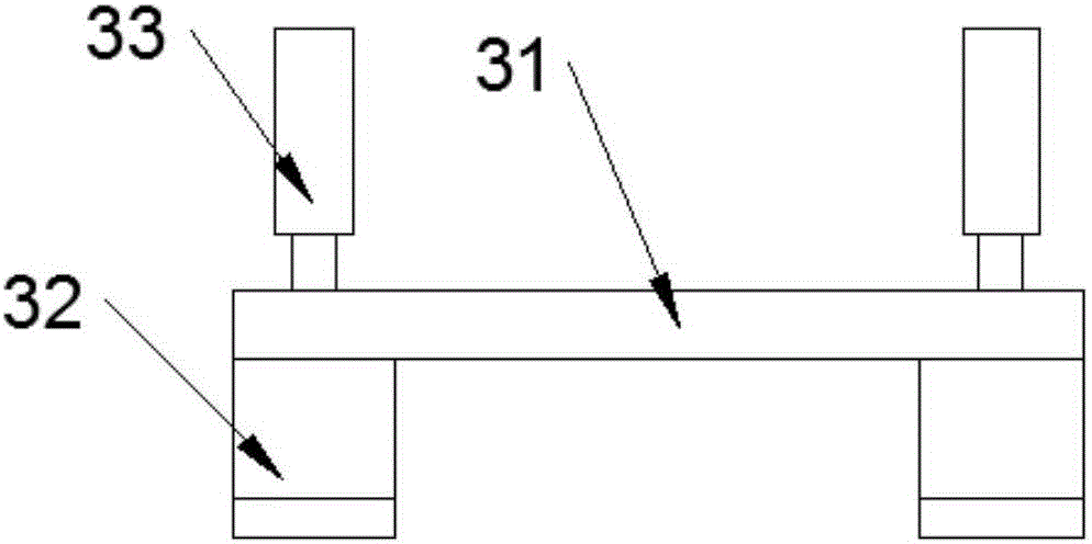
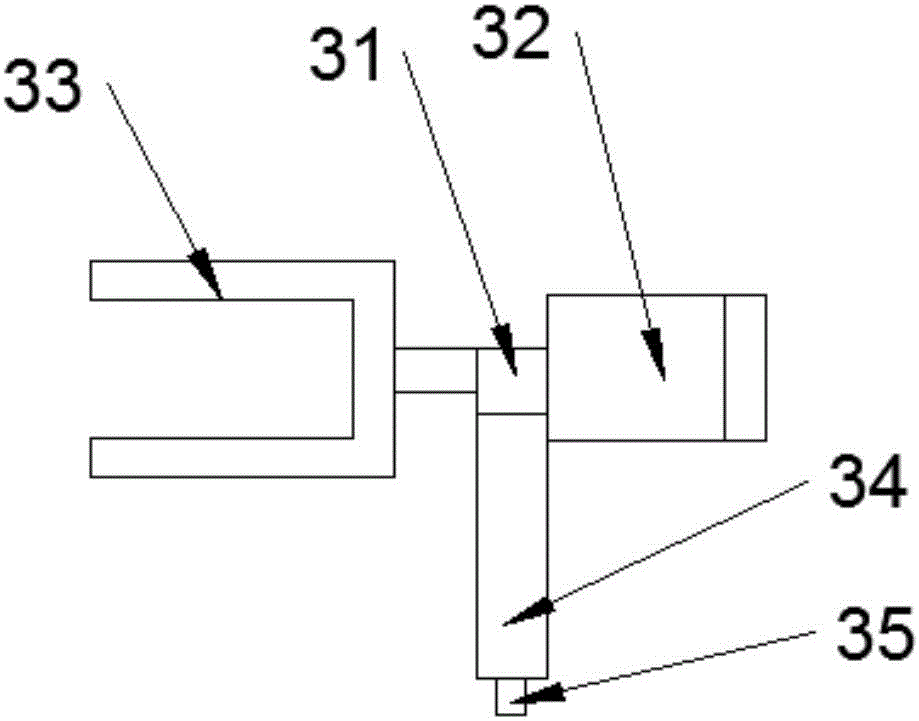
Corrugated pipe machining device

A technology of processing device and bellows, applied in metal processing, positioning device, grinding drive device, etc., can solve the problems of inaccurate processing, low work efficiency, difficult application, etc., and achieve good grinding quality, high work efficiency, Wide range of effects

Inactive Publication Date: 2017-01-04
南昌迪亚汽车波纹管有限公司
View PDF7 Cites 30 Cited by
  • Summary
  • Abstract
  • Description
  • Claims
  • Application Information

AI Technical Summary

Problems solved by technology

Whether it is cutting or grinding the bellows, it is relatively difficult to clamp and position the bellows. If the clamp is too tight, it is easy to deform, and one kind of equipment cannot process bellows with different diameters. The equipment is not universal. If the clamp is loose, it will easily cause inaccurate processing and affect the processing quality. Therefore, in the cutting process, the fixed clamping of the bellows is very important, and most of the current manual clamping devices are difficult to meet. Requirements, and some are processed by CNC machine tools, but their cost is high and it is difficult to be widely used
[0003] In addition, in the prior art, the grinding of pipe joints is done manually by workers, especially for corrugated pipes with special shapes. After the workers clamp the pipe joints with special clamps, they manually put the end faces of the pipe joints on the grinding wheel for grinding. , the two end faces are polished twice, and the work efficiency is low. During the grinding process, the position of the pipe fittings is not stable, and the quality of the grinding is controlled manually, so it is difficult to achieve uniform standards.

Method used


Image

  • Corrugated pipe machining device
  • Corrugated pipe machining device
  • Corrugated pipe machining device

Examples


Embodiment Construction

[0035] It should be noted that, in the case of no conflict, the embodiments of the present invention and the features in the embodiments can be combined with each other.

[0036] In describing the present invention, it should be understood that the terms "center", "longitudinal", "transverse", "upper", "lower", "front", "rear", "left", "right", " The orientations or positional relationships indicated by "vertical", "horizontal", "top", "bottom", "inner" and "outer" are based on the orientations or positional relationships shown in the drawings, and are only for the convenience of describing the present invention and Simplified descriptions, rather than indicating or implying that the device or element referred to must have a particular orientation, be constructed and operate in a particular orientation, and thus should not be construed as limiting the invention. In addition, the terms "first", "second", etc. are used for descriptive purposes only, and should not be understood ...


PUM


Abstract

The invention provides a corrugated pipe machining device. Each adjustment sliding rail is provided with a first adjustment sliding block and a second adjustment sliding block, positioning parts are fixedly connected to the opposite side faces of the first adjustment sliding block and the second adjustment sliding block on the same adjustment sliding rail respectively, a first connecting rod is connected between every two adjacent first adjustment sliding blocks, a second connecting rod is connected between every two adjacent second adjustment sliding blocks, a first nut is connected to the first connecting rod between any two first adjustment sliding blocks, and a second nut is connected to the second connecting rod corresponding to the first connecting rod. The corrugated pipe machining system can conduct cutting and grinding on a corrugated pipe, positioning and fixing on the corrugated pipe are enhanced, the corrugated pipe machining device is suitable for clamping and positioning the corrugated pipes with different sizes, the application range is wide, and the machining precision and the uniformity of standards of machined products are guaranteed.

Description

technical field [0001] The invention belongs to the technical field of pipe material processing equipment, and in particular relates to a corrugated pipe processing device. Background technique [0002] Bellows is a circular profile with a corrugated outer circumference and uneven surface. Bellows are widely used in petrochemical, instrumentation, aerospace, chemical, electric power, cement, metallurgy, etc. industry. Whether it is cutting or grinding the bellows, it is relatively difficult to clamp and position the bellows. If the clamp is too tight, it is easy to deform, and one kind of equipment cannot process bellows with different diameters. The equipment is not universal. If the clamp is loose, it will easily cause inaccurate processing and affect the processing quality. Therefore, in the cutting process, the fixed clamping of the bellows is very important, and most of the current manual clamping devices are difficult to meet. Requirements, and some are processed by ...

Claims


Application Information

Patent Timeline
IPC IPC(8): B24B9/00B24B41/06B24B41/02B24B41/00B24B27/00B24B47/10B26D7/02B23P23/04B23Q3/06
CPCB23P23/04B23Q3/06B24B9/007B24B27/0076B24B41/005B24B41/02B24B41/06B24B47/10B26D7/02
Inventor 唐丽伟
Owner 南昌迪亚汽车波纹管有限公司
Learn More