
High-gain low-noise optimal bias regulating type cascode trans-impedance amplifier

A technology of transimpedance amplifier and cascode, which is applied in the fields of optical communication, optical interconnection and visible light communication, can solve the problem that the noise performance cannot be significantly improved, reduce the equivalent input noise current and improve the transimpedance gain. , the effect of reducing circuit noise

Inactive Publication Date: 2016-12-21
TIANJIN UNIV
View PDF3 Cites 13 Cited by
  • Summary
  • Abstract
  • Description
  • Claims
  • Application Information

AI Technical Summary

Problems solved by technology

For example, improved methods such as parallel inductor peaking, parallel double feedback, and pre-equalization are introduced. However, most of these technologies only increase the circuit bandwidth, but the noise performance has not been significantly improved.

Method used


Image

  • High-gain low-noise optimal bias regulating type cascode trans-impedance amplifier
  • High-gain low-noise optimal bias regulating type cascode trans-impedance amplifier
  • High-gain low-noise optimal bias regulating type cascode trans-impedance amplifier

Examples


Embodiment 1

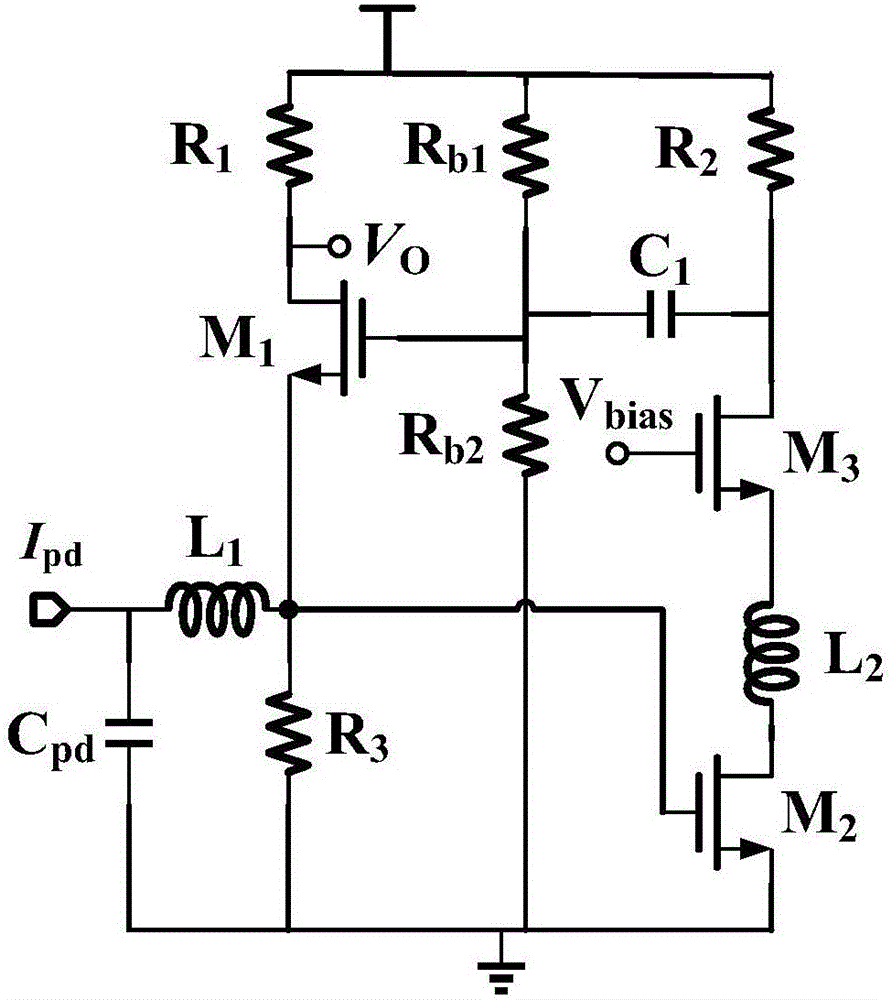
[0025] see figure 1 , the embodiment of the present invention provides a cascode transimpedance amplifier with high gain, low noise and optimal bias adjustment, that is, an auxiliary cascode amplifier is used in the RGC transimpedance amplifier to increase the transimpedance gain of the circuit; The π-type matching network is used to reduce the influence of parasitic capacitance on the bandwidth; the optimal bias circuit is used to make the RGC main amplifier and auxiliary amplifier work in the best state, and to avoid the mutual influence of the DC bias of the two, see the following description for details:

[0026] 1. Between the output terminal of the auxiliary amplifier and the gate of the main amplifier, a bias circuit with a high-pass filter structure is added to isolate the DC bias of the RGC main amplifier and the auxiliary amplifier, so that both work at the best bias set state.

[0027] 2. Use a cascode amplifier to replace the common-source amplifier in the traditi...

Embodiment 2

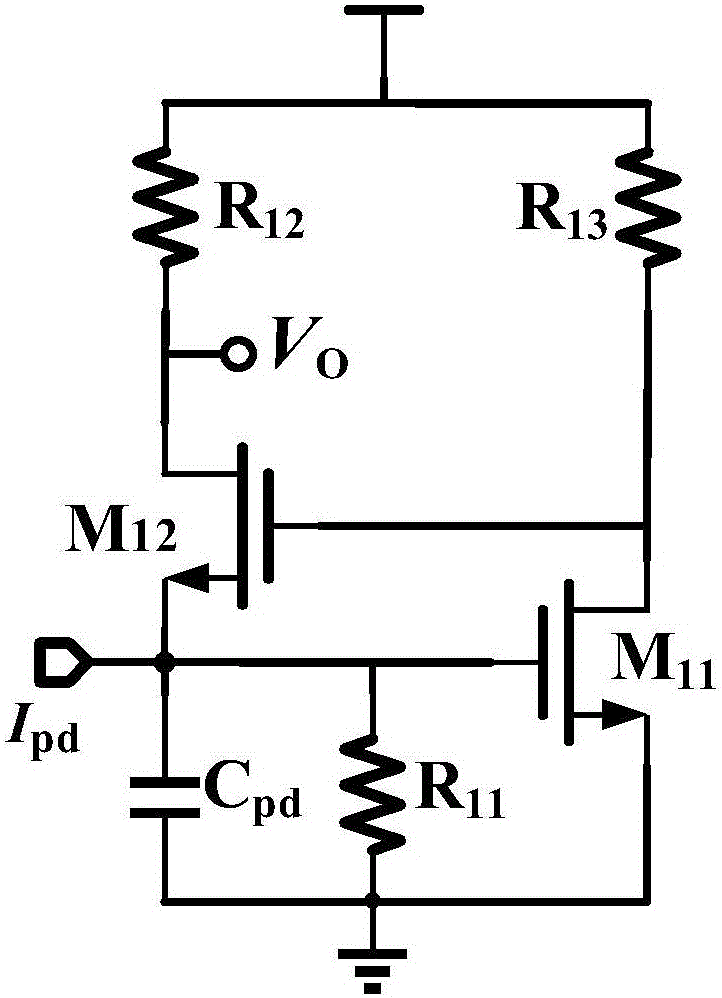
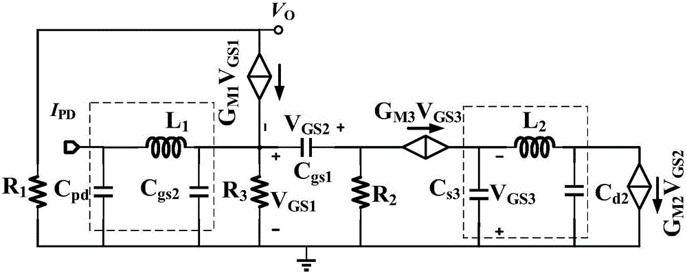
[0031] Combine below figure 2 , image 3 The scheme in embodiment 1 is described in detail, see below for details:

[0032] figure 2 Shown is the circuit schematic diagram of the classic RGC transimpedance amplifier, which is composed of two parts: the main amplifier and the auxiliary amplifier. Its main function is to receive the weak current signal output by the photodetector, and convert and amplify it into a voltage signal. When the output current of the photodetector flows into the input terminal of the classic RGC transimpedance amplifier, it is amplified by the main amplifier and the auxiliary amplifier, converted into a voltage signal, and output from the output terminal.

[0033] Theoretically speaking, as long as the parameters of the components in the circuit are adjusted so that the main amplifier and the auxiliary amplifier respectively achieve the best amplitude-frequency characteristics, the performance of the classic RGC transimpedance amplifier can be opt...

Embodiment 3

[0060] Figure 4 Simulation results for a preferred embodiment of an optimally biased RGC transimpedance amplifier. The results show that the transimpedance gain of the optimally biased RGC structure reaches 60.5dB, and the -3dB bandwidth is 5GHz. The input noise current density of the improved circuit is about 5pA lower than that of the traditional RGC structure, and the noise within the working bandwidth is less than 8.6pA / √Hz. Therefore, the transimpedance amplifier circuit described in the embodiment of the present invention can achieve high gain and low noise.


PUM


Abstract

The invention discloses a cascode transimpedance amplifier with high gain, low noise and optimal bias adjustment, which includes: a main amplifier and an auxiliary amplifier, and also includes: a connection between the output terminal of the auxiliary amplifier and the gate of the main amplifier In between, a bias circuit with a high-pass filter structure is added to isolate the DC bias of the main amplifier and the auxiliary amplifier, so that both work in the best bias state; a cascode amplifier is used to replace the DC bias in the auxiliary amplifier Common-source stage amplifier, providing higher gain-bandwidth product; series inductor L at the input 1 , the series inductor L between the common-source and common-gate devices of the cascode amplifier 2 , the two inductances, the photodetector capacitance at the input end and the parasitic capacitance of the MOS tube form two π-type matching networks respectively. On the premise of ensuring that the overall bandwidth of the transimpedance amplifier is not reduced, the present invention improves the circuit gain and reduces noise, and finally realizes the RGC transimpedance amplifier with high gain and low noise.

Description

technical field [0001] The invention relates to the fields of optical communication, optical interconnection and visible light communication, in particular to a cascode transimpedance amplifier with high gain and low noise and optimal bias adjustment. Background technique [0002] With the exponential growth of human society's demand for network bandwidth and data traffic, breakthroughs have been made in ultra-high-speed, ultra-large-capacity optical fiber communication technology for trunk network transmission, but in the cabinets of optical network switching nodes, between circuit boards, Short-distance communication between chips and inside chips still uses electronic information processing and exchange methods, resulting in electronic bottlenecks. Therefore, it has become an inevitable trend to replace electrical interconnection with optical interconnection. As the receiving link of the optical communication system, the optical receiver directly affects the overall perf...

Claims


Application Information

Patent Timeline
IPC IPC(8): H03F1/26H03F3/08H03G3/30
CPCH03F1/26H03F3/082H03G3/3084
Inventor 谢生吴思聪毛陆虹陶希子高谦
Owner TIANJIN UNIV
Learn More