Turnout sliding plate and manufacturing method
A technology of sliding bed and turnout, applied in the direction of track, road, coating, etc., can solve the problems of low wear resistance and impact resistance, poor corrosion resistance, etc., and achieve the effect of good friction performance
- Summary
- Abstract
- Description
- Claims
- Application Information
AI Technical Summary
Problems solved by technology
Method used
Image

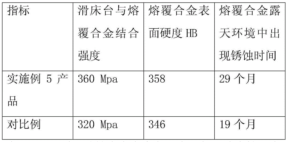
Examples
preparation example Construction
[0027] The preparation method of the turnout sliding bed mainly includes the following steps:
[0028] 1. Sand blasting to remove scale, rust and oil stains on the surface of the sliding bed;
[0029] 2. Preparation of cladding alloy powder materials;
[0030] 3. Cladding parameter input of sliding bed;
[0031] 4. Quality inspection and parameter adjustment of alloy powder surfacing cladding on slide bed;
[0032] 5. Plasma arc alloy powder surfacing cladding on sliding bed;
[0033] 6. Cladding quality inspection of turnout sliding bed;
[0034] 7. Plasma arc powder surfacing cladding parameters of turnout sliding bed:
[0035] Current = 160-300A;
[0036] Protective gas flow = 2 ~ 12L / min;
[0037] Powder feeding air flow = 0.5 ~ 2L / min;
[0038] One surfacing welding width = 3-24mm;
[0039] One-time surfacing thickness = 2-6mm;
[0040] One surfacing welding speed = 200-600mm / min.
Embodiment 1
[0043] Carry out pretreatment on the material of Q235 sliding bed, and remove the rust, oil and scale on the table by sandblasting. Prepare cladding alloy powder, the powder particle size is 150 mesh, the mass percentage of the cladding alloy powder is: C 0.25%, B 3.5%, Si 3%, Ni 2.0%, Cr 12.5%, rare earth ferrosilicon alloy 1.50%, the balance For Fe. Plasma arc powder surfacing welding machine is used to surfacing and cladding the sliding bed, welding current = 160A, powder feeding gas flow rate = 0.5L / min, shielding gas flow rate = 2L / min, a surfacing welding width = 3mm; a surfacing welding Thickness = 2mm; once surfacing welding speed = 600mm / min. The sliding bed and the deposited alloy are metallurgically bonded.
Embodiment 2
[0045] Carry out pretreatment on the material of Q275 sliding bed, and remove the rust, oil and scale on the table by sandblasting. Prepare cladding alloy powder, the powder particle size is 300 mesh, the mass percent of the cladding alloy powder is: C 0.20%, B 3.5%, Si 3%, Ni 2.8%, Cr 16.0%, rare earth ferrosilicon 1.50%, the balance For Fe. Plasma arc powder surfacing machine is used to surfacing and cladding the sliding bed, welding current = 180A, powder feeding gas flow rate = 0.8L / min, shielding gas flow rate = 4L / min, a surfacing welding width = 8mm; a surfacing welding Thickness = 3mm; one surfacing welding speed = 500mm / min. The sliding bed and the deposited alloy are metallurgically bonded.
PUM
 Abstract
Description
Claims
Application Information
 - R&D
- Intellectual Property
- Life Sciences
- Materials
- Tech Scout
- Unparalleled Data Quality
- Higher Quality Content
- 60% Fewer Hallucinations
Browse by: Latest US Patents, China's latest patents, Technical Efficacy Thesaurus, Application Domain, Technology Topic, Popular Technical Reports.
© 2025 PatSnap. All rights reserved.Legal|Privacy policy|Modern Slavery Act Transparency Statement|Sitemap|About US| Contact US: help@patsnap.com