Novel ultra-low-loss microwave dielectric ceramic material and preparation method thereof
A microwave dielectric ceramic, ultra-low technology, applied in the field of ultra-low loss microwave dielectric ceramic materials, can solve problems such as difficult control, deterioration of microwave performance, complex phase composition of material system, etc., achieve stable performance, performance improvement, and increase process complexity Effect
- Summary
- Abstract
- Description
- Claims
- Application Information
AI Technical Summary
Problems solved by technology
Method used
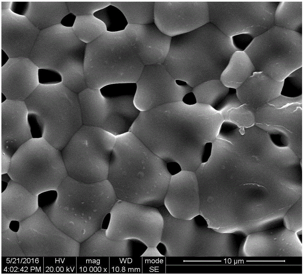
Image


Examples
Embodiment 1
[0034] Step 1: Dosing; as Mg(OH) 2 4MgCO 3 ·5H 2 O (basic magnesium carbonate) 62.64%, Li 2 CO 3 16.79%, TiO 2 17.88% and CaCO 3 2.69% mass percentage batching obtains mixture;
[0035] Step 2: ball milling; the mixture obtained in step 1 is ball milled for the first time to obtain a ball mill, and the specific ball milling process is: using zirconia balls as the ball milling medium, according to the mass ratio of mixture: ball: ethanol is 1: 5: 3. Grind for 7 hours to obtain a uniformly mixed ball mill;
[0036] Step 3: drying and sieving; drying the ball mill material obtained in step 2 and passing it through a 100-mesh sieve to obtain a dry powder;
[0037] Step 4: pre-burning; the dry powder obtained in step 3 is placed in an alumina crucible to pre-fire to obtain a pre-fired powder;
[0038] Step 5: ball milling; ball milling the calcined powder obtained in step 4 or adding a dopant to the calcined powder to obtain a ball milling material after the second ball mil...
Embodiment 2
[0043] Step 1: Dosing; as Mg(OH) 2 4MgCO 3 ·5H 2O (basic magnesium carbonate) 63.56%, Li 2 CO 3 16.69%, TiO 2 17.78% and SrCO 3 1.97% mass percentage batching obtains mixture;
[0044] Step 2: ball milling; the mixture obtained in step 1 is ball milled for the first time to obtain a ball mill, and the specific ball milling process is: using zirconia balls as the ball milling medium, according to the mass ratio of mixture: balls: ethanol is 1: 6: 3. Grind for 7 hours to obtain a uniformly mixed ball mill;
[0045] Step 3: drying and sieving; drying the ball mill material obtained in step 2 and passing it through a 100-mesh sieve to obtain a dry powder;
[0046] Step 4: pre-burning; the dry powder obtained in step 3 is placed in an alumina crucible to pre-fire to obtain a pre-fired powder;
[0047] Step 5: ball milling; ball milling the calcined powder obtained in step 4 or adding a dopant to the calcined powder to obtain a ball mill after the second ball milling, the sp...
Embodiment 3
[0052] Step 1: Dosing; according to Mg(OH) 2 4MgCO 3 ·5H 2 O (basic magnesium carbonate) 62.51%, Li 2 CO 3 16.24%, TiO 2 The mass percent batching of 17.30% and MgO3.00% obtains mixture;
[0053] Step 2: ball milling; the mixture obtained in step 1 is ball milled for the first time to obtain a ball mill, and the specific ball milling process is: using zirconia balls as the ball milling medium, according to the mass ratio of mixture: balls: ethanol is 1: 6: 2. Grind for 7 hours to obtain a uniformly mixed ball mill;
[0054] Step 3: drying and sieving; drying the ball mill material obtained in step 2 and passing it through a 100-mesh sieve to obtain a dry powder;
[0055] Step 4: pre-burning; the dry powder obtained in step 3 is placed in an alumina crucible to pre-fire to obtain a pre-fired powder;
[0056] Step 5: ball milling; ball milling the calcined powder obtained in step 4 or adding a dopant to the calcined powder to obtain a ball mill after the second ball milli...
PUM
| Property | Measurement | Unit |
|---|---|---|
| Resonant frequency temperature coefficient | aaaaa | aaaaa |
Abstract
Description
Claims
Application Information
 - Generate Ideas
- Intellectual Property
- Life Sciences
- Materials
- Tech Scout
- Unparalleled Data Quality
- Higher Quality Content
- 60% Fewer Hallucinations
Browse by: Latest US Patents, China's latest patents, Technical Efficacy Thesaurus, Application Domain, Technology Topic, Popular Technical Reports.
© 2025 PatSnap. All rights reserved.Legal|Privacy policy|Modern Slavery Act Transparency Statement|Sitemap|About US| Contact US: help@patsnap.com