
Long wave infrared optical athermalization temperature measuring lens with ultra-large view field and manufacturing method thereof

A technology of infrared optics and manufacturing methods, applied in the directions of optical radiation measurement, optics, optical components, etc., can solve the problem that the imaging field angle is small and the overall structure, concentricity, precision and axial position of the test object cannot be obtained completely, and the optical System focal length change and other problems, to achieve the effect of accuracy and axial position accuracy, high resolution, simple design structure

Active Publication Date: 2016-11-16
FUJIAN FUGUANG TIANTONG OPTICS
View PDF4 Cites 7 Cited by
  • Summary
  • Abstract
  • Description
  • Claims
  • Application Information

AI Technical Summary

Problems solved by technology

Because infrared optical materials and mechanical materials will produce thermal deformation when the temperature changes, the drastic change of working temperature will cause the focal length change of the optical system, the image surface is elegant, and the image quality is reduced.
In order to eliminate or reduce the impact of temperature changes on the imaging of the optical system, corresponding compensation techniques must be used to keep the focal length of the optical system unchanged within a large temperature range to ensure good imaging quality. In addition, existing lenses have imaging The small field of view cannot completely obtain the overall structure of the test object. In addition, the inaccuracy of concentricity, precision and axial position also affects the implementation of compensation technology

Method used


Image

  • Long wave infrared optical athermalization temperature measuring lens with ultra-large view field and manufacturing method thereof
  • Long wave infrared optical athermalization temperature measuring lens with ultra-large view field and manufacturing method thereof

Examples


Embodiment Construction

[0021] The present invention will be further described below in conjunction with the accompanying drawings and specific embodiments.

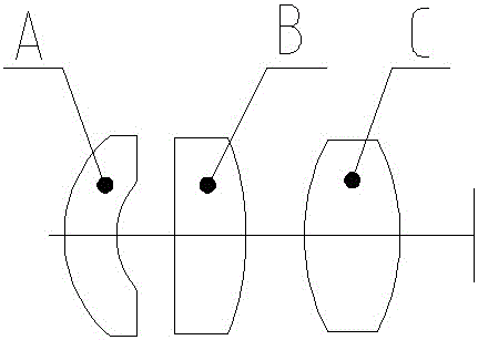
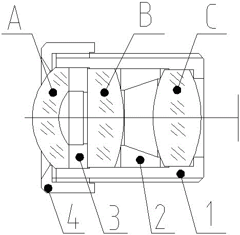
[0022] Such as Figure 1~2 Shown is an ultra-large field of view long-wave infrared optical athermalization temperature measurement lens. The optical system of the lens is provided with a negative crescent lens A, a plano-convex lens B, and a double-convex lens C in sequence along the incident direction of light from left to right.

[0023] In this embodiment, the air gap between the negative crescent lens and the plano-convex lens B is 2.8 mm, and the air gap between the plano-convex lens B and the biconvex lens C is 3 mm.

[0024] In this embodiment, the mechanical structure of the lens is mainly the main lens barrel 1, and the lenses are sequentially assembled into the main lens barrel in the order of C, B, and A, and the negative crescent lens A and the plano-convex lens B are connected by a second The spacer 3 is positioned, the first spa...


PUM


Abstract

The invention relates to a long wave infrared optical athermalization temperature measuring lens with an ultra-large view field. The optical system of the lens is sequentially provided with the following components in the light incidence direction from left to right: a negative moon shape lens (A), a plano-convex lens (B), and a double convex lens (C), which are made of different materials. The provided lens has the advantages of large relative aperture, ultra-wide field angle, low deformation, self-adaptive optical athermalization compensation, and light structure. The difference of refractive index change of an optical material under different temperatures is used to compensate the influence of temperature change on a focal plane; thus the structure of athermalization design becomes simpler, the structure of overall product becomes smaller, the weight becomes lighter, the optical axis is stable, the image becomes clearer, the reliability is high, the requirements of imaging performance of customers can be met, and the structure is convenient to use for the customers.

Description

technical field [0001] The invention relates to the technical field of optical lens devices, in particular to an ultra-large field of view long-wave infrared optical athermalization temperature measurement lens and a manufacturing method thereof. Background technique [0002] As a non-contact temperature measurement technology, infrared temperature measurement technology has many advantages compared with traditional temperature measurement technology. First, its measurement does not interfere with the temperature measurement field, does not affect the temperature distribution, and has high accuracy and precision; secondly, Infrared temperature measurement is fast and can be observed in real time, which has great advantages in measurement; thirdly, infrared temperature measurement can be near or far, and can work at night, with strong adaptability; finally, infrared temperature measurement has a wide range and theoretically has no upper limit for testing. This makes infrared ...

Claims


Application Information

Patent Timeline
IPC IPC(8): G01J5/08G01J5/02G02B13/06G02B13/14
CPCG02B13/06G02B13/14G01J5/0806G01J2005/0077G01J5/068G01J5/0808
Inventor 刘涛何武强陈潇魏泽岚林佳丽
Owner FUJIAN FUGUANG TIANTONG OPTICS
Learn More