A kind of plasma cladding manufacturing 3D printing equipment and method

A technology of plasma cladding and 3D printing, which is used in processing and manufacturing, manufacturing tools, additive manufacturing, etc., and can solve the problems of high laser price, uneven surface of parts, and low mechanical properties of three-dimensional metal parts.

Active Publication Date: 2018-10-23
中研碧诚(北京)科技有限公司
View PDF8 Cites 0 Cited by
  • Summary
  • Abstract
  • Description
  • Claims
  • Application Information

AI Technical Summary

Problems solved by technology

This makes SLM rapid prototyping equipment expensive to run
[0007] Third, the laser is the core component of the selective laser rapid prototyping equipment, but the price of the laser is high and the maintenance cost is high
However, the above-mentioned laser cladding molding equipment and method mainly have the following three problems: first, the laser cannot protect the droplet, and a protective gas needs to be passed at the wire feeder. Forming has adverse effects, resulting in low mechanical properties of three-dimensional metal parts; second, the laser power is low and the diameter of the metal wire is large, it is difficult to achieve rapid prototyping of ceramic and composite material parts; third, due to surface tension, droplet cooling Circular shrinkage occurs during solidification molding, resulting in rough surface of the part

Method used


Image

  • A kind of plasma cladding manufacturing 3D printing equipment and method
  • A kind of plasma cladding manufacturing 3D printing equipment and method
  • A kind of plasma cladding manufacturing 3D printing equipment and method

Examples


Embodiment 2

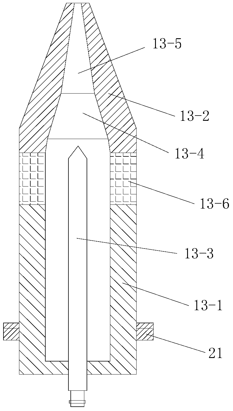
[0148] In this example, if Figure 7 As shown, the difference between the plasma cladding manufacturing 3D printing equipment used and the embodiment 1 is that the angle between the nozzle 13-5 and the central axis of the gun body 13-1 is 30°-45°.

[0149] In this way, after changing the direction of the plasma beam through the nozzle 13-5, the thermal load impact of the plasma jet on the anode nozzle 13-2 can be effectively reduced, and the anode ablation condition is improved.

[0150] In this embodiment, the structure, connection relationship and working principle of the rest of the 3D printing equipment manufactured by plasma cladding are the same as those in Embodiment 1.

[0151] In this embodiment, the plasma cladding manufacturing 3D printing method used is the same as that in Embodiment 1.


PUM

PropertyMeasurementUnit
heightaaaaaaaaaa

Abstract

The invention discloses a plasma cladding manufacturing 3D printing equipment and method. The equipment is composed of a monitoring system, a plasma beam processing system and a horizontal printing platform for placing workpieces to be printed; the plasma beam processing system consists of a plasma generator, It consists of a gas supply device, a powder feeding device that feeds powder into the plasma beam, and a printing position adjustment device; the monitoring system includes a position adjustment controller, a temperature detection unit, a distance detection unit, and a printing distance adjustment controller. The temperature detection unit and the printing distance The temperature control device is composed of an adjustment controller; the method includes steps: 1. acquisition of a three-dimensional model of the workpiece to be printed and layered slice processing; 2. filling of the scanning path; 3. acquisition of the printing path; 4. printing layer by layer from bottom to top. The invention is reasonable in design, easy to operate, high in molding efficiency and good in use effect, does not need a closed molding chamber, and does not need a protective atmosphere or a vacuum environment, and the workpiece molding process is directly carried out in an atmospheric environment.

Description

technical field [0001] The invention belongs to the technical field of rapid prototyping, and in particular relates to a plasma cladding manufacturing 3D printing equipment and method. Background technique [0002] 3D printing, known as Additive Manufacturing (AM) in academic circles, is a technology that uses computer design data to manufacture physical objects by layer-by-layer accumulation of materials. This technology started from the rapid prototyping technology in the 1980s and has three characteristics: one is a major leap in manufacturing technology. 3D printing is an emerging digital manufacturing technology that was born out of the integration of digital technology and manufacturing technology; the second is a profound change in the manufacturing process. 3D printing has changed the traditional cutting process mode, greatly reduced the processing steps, and can significantly shorten the development cost and cycle of new products; the third is an important breakthr...

Claims


Application Information

Patent Timeline
Patent Type & Authority Patents(China)
IPC IPC(8): B29C64/153B29C64/209B29C64/321B29C64/236B29C64/264B29C64/393B33Y10/00B33Y30/00B33Y40/00B33Y50/02B22F10/28B22F10/31B22F12/00B22F12/41B22F12/50B22F12/53B22F12/70B22F12/90
Inventor 华云峰
Owner 中研碧诚(北京)科技有限公司
Why Eureka
Try Eureka