
Methane recovery system and recovery method

A recovery system, methane technology, applied in the field of recovery of boil-off gas (BOG), can solve the problem of low recovery efficiency and achieve the effect of achieving safety and recovery efficiency

Inactive Publication Date: 2016-08-10
ENN SCI & TECH DEV
View PDF7 Cites 0 Cited by
  • Summary
  • Abstract
  • Description
  • Claims
  • Application Information

AI Technical Summary

Problems solved by technology

[0005] For this reason, the technical problem to be solved by the present invention is to overcome the problem of low recovery efficiency when recovering and releasing methane in the prior art so as to provide a methane recovery system that can not only improve the recovery rate, but also make the liquid production system and the liquid discharge system run independently and smoothly. System and recovery method

Method used


Image

  • Methane recovery system and recovery method
  • Methane recovery system and recovery method
  • Methane recovery system and recovery method

Examples


Embodiment 1

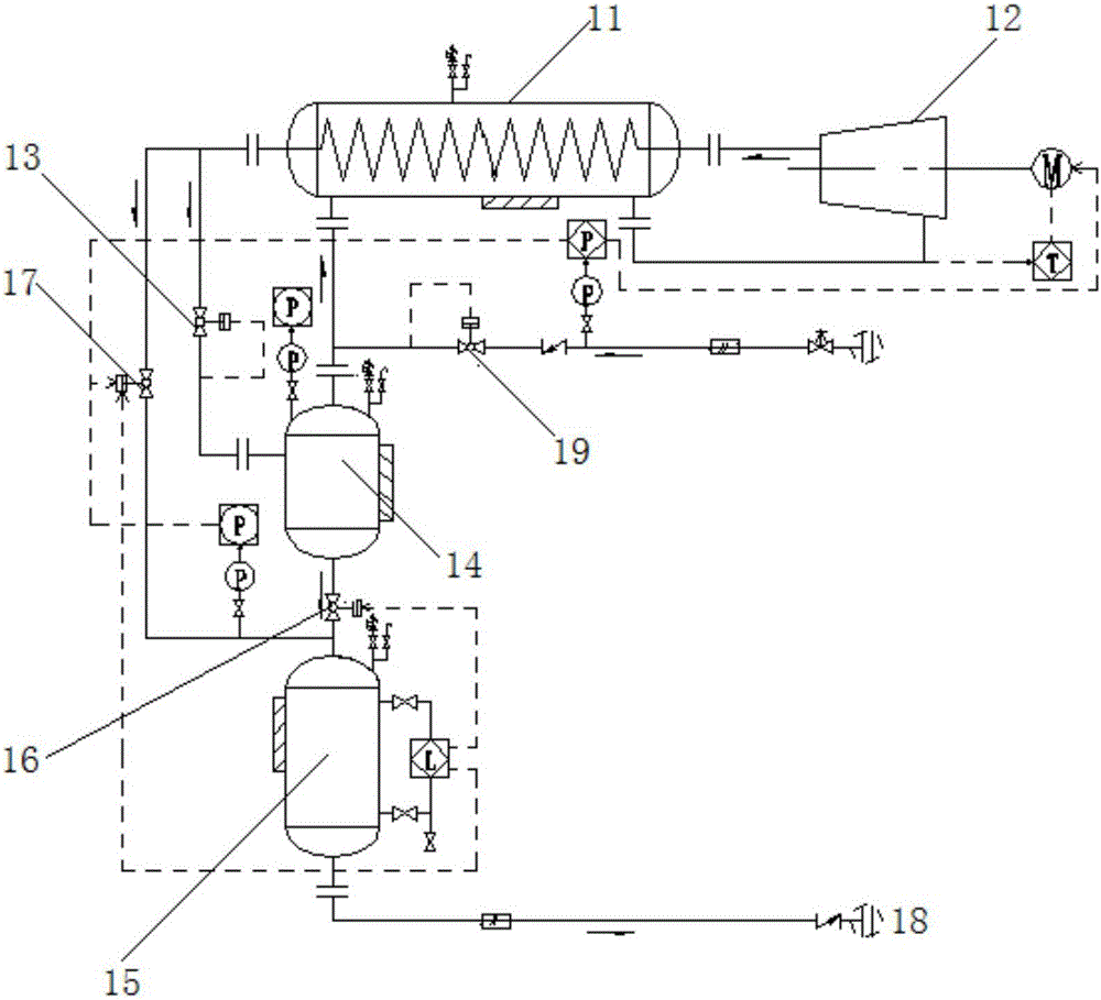
[0024] like figure 1 As shown, this embodiment provides a methane recovery system, the system includes a heat exchange device 11 for receiving methane gas, and the heat exchange device 11 includes at least two channels, wherein the inlet of the first channel is connected to the gas-liquid separation device 14, the outlet of the first passage is connected with the inlet of the compression device 12, the inlet of the second passage is connected with the outlet of the compression device 12, and the outlet of the second passage is connected with the gas outlet through the throttling and stabilizing device 13. The inlet of the liquid separation device 14 is connected, the liquid outlet of the gas-liquid separation device 14 is connected with the inlet of the liquid storage tank 15, and the liquid outlet of the gas-liquid separation device 14 is connected to the inlet of the liquid storage tank 15. A cut-off valve 16, the liquid storage tank 15 is provided with a booster port, the b...

Embodiment 2

[0032] Embodiment 2 is an improvement made on the basis of Embodiment 1. In order to improve the system for recovering methane gas, the methane liquid discharged from the liquid storage tank 15 is improved on the system of Embodiment 1. The following details:

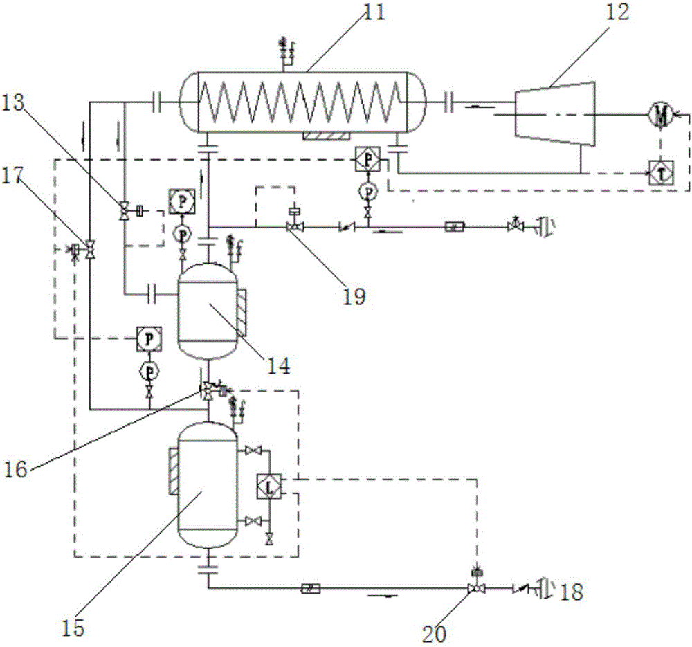
[0033] like figure 2 As shown, in order to better control the discharge of the methane liquid, the outlet of the liquid storage tank 15 is connected to the liquid inlet of the methane storage tank 18 through a liquid discharge valve 20, and the liquid level of the liquid storage tank 15 reaches a predetermined When within the range, close the cut-off valve 16, stop methane liquid from flowing into the liquid storage tank 15 from the gas-liquid separation device 14, then open the liquid discharge valve 20, and finally gradually open the booster valve 17, through The pressure boost valve 17 adjusts the pressure of the liquid storage tank 15, thereby facilitating liquid discharge; when the liquid level of the liquid stora...

Embodiment 3

[0035] Embodiment 3 is an improvement made on the basis of Embodiment 1 or Embodiment 2. In order to meet the requirements for the gas to enter the compression device, the system of Embodiment 1 or Embodiment 2 controls the gas before entering the compression device. Improvements are made in detail below:

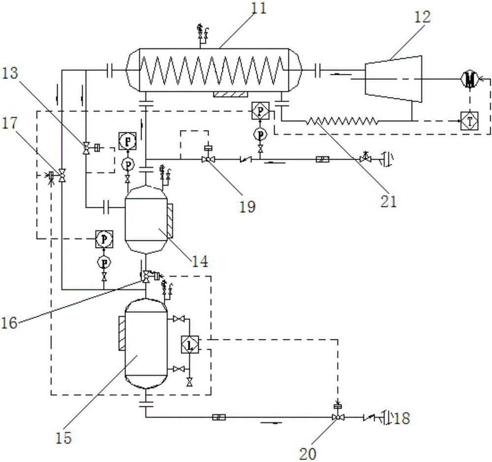
[0036] like image 3 As shown, in order to ensure that the outlet gas of the first passage of the heat exchange device 11 meets the requirements of the inlet of the compression device 12, the outlet of the first passage of the heat exchange device 11 passes through the heater 21 and the inlet of the compression device 12 connected, the heater 21 is used to heat the methane gas discharged from the first channel of the heat exchange device 11 to increase the temperature of the gas, thereby helping to meet the temperature requirements of the compression device 12 for the inlet gas.


PUM


Abstract

The invention relates to a methane recovery system and recovery method, the system includes a heat exchange device for receiving methane gas, the heat exchange device includes at least two channels, wherein the inlet of the first channel is connected with the gas outlet of the gas-liquid separation device , the outlet of the first passage is connected with the inlet of the compression device, the inlet of the second passage is connected with the outlet of the compression device, and the outlet of the second passage is connected with the inlet of the gas-liquid separation device through a throttling and stabilizing device, so A cut-off valve is provided between the liquid outlet of the gas-liquid separation device and the inlet of the liquid storage tank, and the liquid storage tank is provided with a booster port, and the booster port is connected to the heat exchange device through the booster valve. The outlet of the second passage is connected, and the cut-off valve and the boost valve control the liquid discharge of the liquid storage tank. The liquid production system and the liquid discharge system of the invention operate separately, and at the same time, the safety of the process and the recovery efficiency are realized through the control means.

Description

technical field [0001] The invention relates to the technical field of gas recovery and reuse, in particular to the recovery of boil-off gas (BOG) applied in the storage and transportation of liquefied natural gas (LNG). Background technique [0002] The main component of liquefied natural gas (LNG) is methane. It is recognized as the cleanest energy source on earth. It is colorless, odorless, non-toxic and non-corrosive. Its volume is about 1 / 625 of the volume of the same amount of gaseous natural gas. The weight of LNG Only about 45% of the same volume of water. Liquefied natural gas is natural gas that becomes liquid after being compressed and cooled to its boiling point. Usually, liquefied natural gas is stored in a low-temperature storage tank at minus 161.5 degrees Celsius and about 0.1 MPa. It is transported by special ships or tank trucks and re-gasified when used. . The burning of liquefied natural gas causes very little air pollution and releases a lot of heat, s...

Claims


Application Information

Patent Timeline
Patent Type & Authority Applications(China)
IPC IPC(8): F17C5/02F17C13/04F17C13/00
CPCF17C5/02F17C13/00F17C13/04F17C2221/033F17C2223/0161F17C2265/037
Inventor 桂谢文李庆堂焦彬端邓义林
Owner ENN SCI & TECH DEV
Learn More