A low-pressure lost-wax precision casting system

A precision casting and low-pressure casting machine technology, applied to casting molding equipment, casting molds, casting mold components, etc., can solve the problems of casting air hole defects, too late to discharge, mold sand collapse, etc., to reduce production costs, facilitate dumping, and ensure sealing effect of effect

Active Publication Date: 2018-05-22
YANGZHOU FENG MING METAL PROD
View PDF7 Cites 0 Cited by
  • Summary
  • Abstract
  • Description
  • Claims
  • Application Information

AI Technical Summary

Problems solved by technology

However, this method has the following disadvantages: (1) Generally, investment casting shells are poured at a higher temperature of the shell itself, so that the filling of the thin-walled shell can be ensured.
(2) This process needs to consume a large amount of resin sand, and the price of resin sand is relatively expensive, which increases the production cost
(3) It takes a long time for resin sand to solidify, which affects production efficiency
⑷When the alloy liquid passes through the resin sand, the resin will be heated, and a large amount of gas will be generated. After the gas enters the cavity, part of it will not be discharged in time and enter the casting, resulting in the formation of pore defects in the casting.
(5) Long-term baking of the resin sand near the gate will easily consume the resin and lead to the collapse of the molding sand. The collapsed molding sand will enter the low-pressure casting holding furnace through the riser pipe. When pouring again, the molding sand in the furnace will enter the subsequent pouring Inside the casting, there are defects such as sand holes in the casting

Method used


Image

  • A low-pressure lost-wax precision casting system
  • A low-pressure lost-wax precision casting system
  • A low-pressure lost-wax precision casting system

Examples


Embodiment Construction

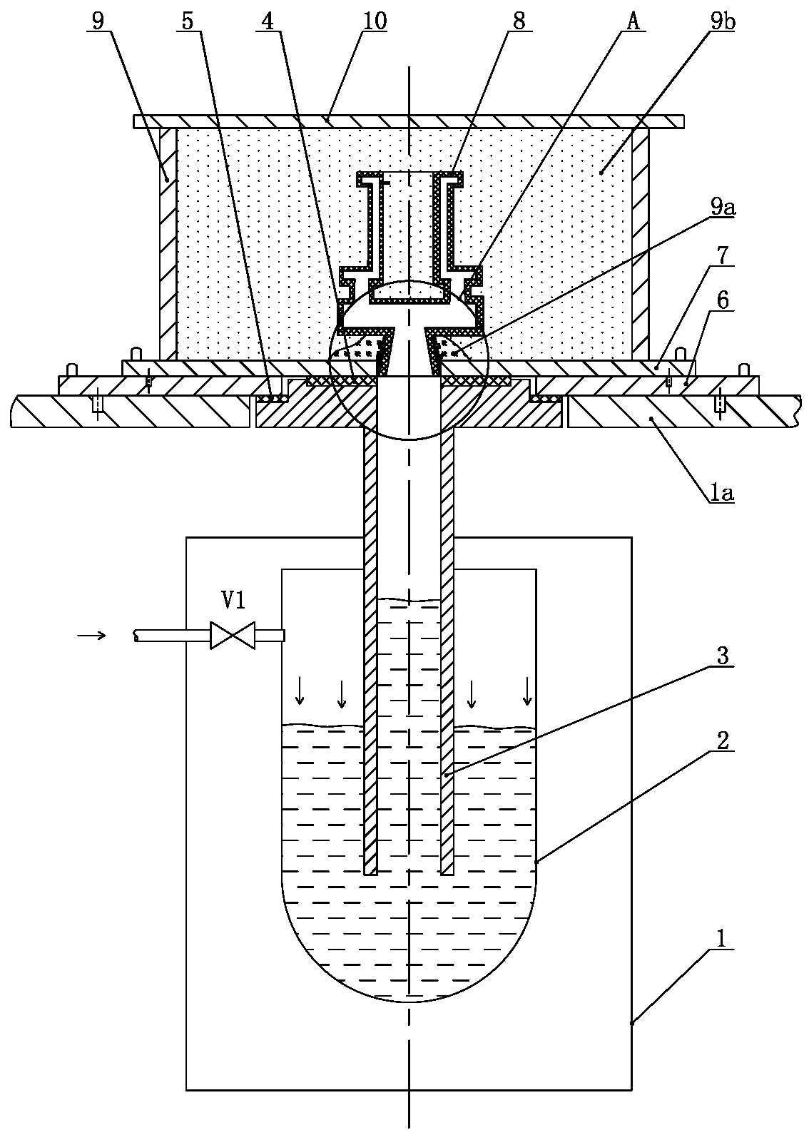
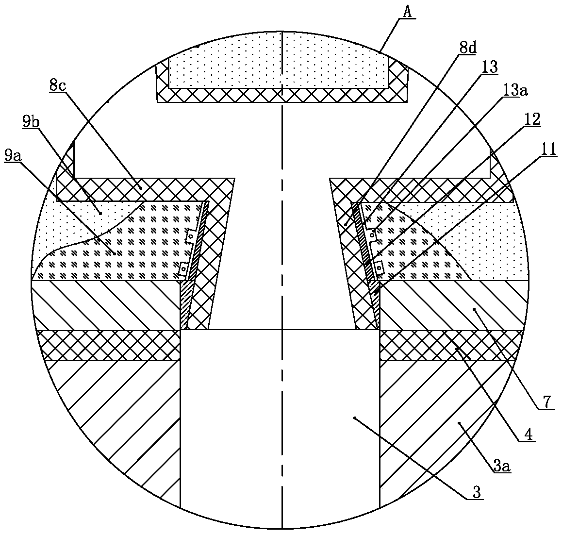
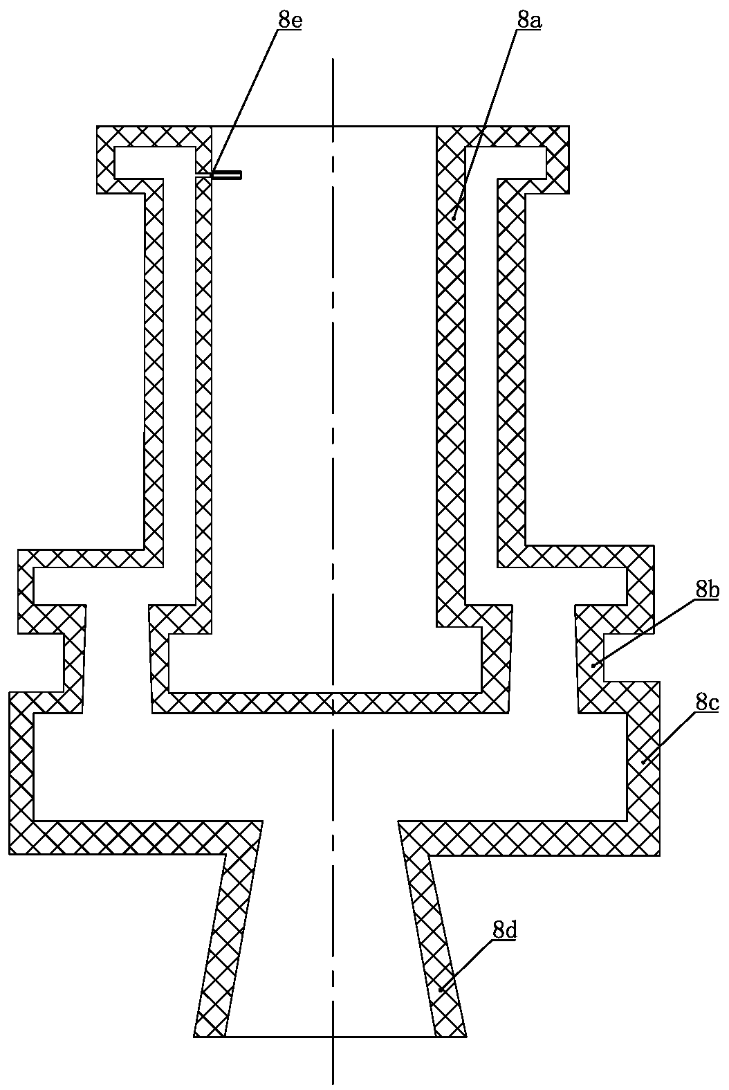
[0035] Such as Figure 1 to Figure 3 As shown, the low-pressure lost-wax investment casting system of the present invention includes a holding furnace 2 located in a low-pressure casting machine 1, a liquid riser 3 is inserted in the liquid phase space of the holding furnace 2, and the side wall of the gas phase space of the holding furnace 2 passes through an air inlet valve. V1 is connected to the compressed air pipe. The top of the liquid riser pipe 3 extends out of the holding furnace 2 and is located in the center hole of the workbench 1a of the low-pressure casting machine. A hoisting steel plate 6 is fixed above the workbench of the low-pressure casting machine, and the top of the hoisting steel plate 6 is fixed. There is a molding steel plate 7, a sand box 9 is fixed above the molding steel plate 7, the top of the sand box 9 is covered with a compression steel plate 10, and a compression device is pressed on the top of the compression steel plate 10, and the inner cavit...


PUM


Abstract

The invention discloses a precise low-pressure lost wax casting system, which comprises a heat holding furnace positioned in a low-pressure casting machine. A riser tube is inserted in the heat holding furnace. The top of the riser tube extends out of the heat holding furnace and is positioned in a center hole of a working table of the low-pressure casting machine. A hoisting steel plate is fixed on the working table of the low-pressure casting machine. A modeling steel plate is fixed on the hoisting steel plate. A sand box is fixed on the modeling steel plate. A pressing steel plate covers the top end of the sand box. A pressing device is pressed on the pressing steel plate. A combined shell is arranged in the center of the inner cavity of the sand box, is coaxial to the riser tube, and comprises a thin-wall product shell, an inner gate shell, a cross gate shell and a sprue cup shell, which are sequentially arranged from top to bottom in a penetrating manner. The lower end opening of the sprue cup shell is formed in the center hole of the modeling steel plate and is in butt joint with the upper end opening of the riser tube hermetically. The periphery of the combined shell and the inner space of the thin-wall product shell are filled with dry sand. The system has the advantages that a thin-wall product can be molded at high temperature, the cost is low, the efficiency is high, and defects are few.

Description

technical field [0001] The invention relates to a casting system, in particular to a low-pressure lost-wax precision casting system, which belongs to the technical field of metal casting. Background technique [0002] Investment casting is also known as lost wax casting. The production process of lost wax casting is to coat several layers of refractory material on the surface of the wax mold. After it is hardened and dried, the wax mold is melted to form a shell, and then baked to shape. , and then pouring, and castings are obtained after cooling. Since the obtained castings have high dimensional accuracy and surface finish, it is also called investment precision casting. [0003] Low-pressure casting is a method of filling the cavity with liquid metal under pressure to form a casting. The process of low-pressure casting is as follows: dry compressed air is introduced into the closed holding furnace, and the molten metal in the holding furnace rises along the liquid riser ...

Claims


Application Information

Patent Timeline
Patent Type & Authority Patents(China)
IPC IPC(8): B22C9/04B22D18/04B22C9/08
CPCB22C9/04B22C9/082B22D18/04
Inventor 眭怀明刘永长肖亮陈冬梅贺从波
Owner YANGZHOU FENG MING METAL PROD
Why Eureka
Try Eureka