A semi-regenerative catalytic reforming reaction system and method

A catalytic reforming and reaction system technology, applied in the fields of naphtha catalytic reforming, petroleum industry, hydrocarbon oil treatment products, etc. The effect of reducing

Active Publication Date: 2017-08-25
石玉林
View PDF7 Cites 0 Cited by
  • Summary
  • Abstract
  • Description
  • Claims
  • Application Information

AI Technical Summary

Problems solved by technology

[0019] The purpose of the present invention is to provide a novel semi-regenerative catalytic reforming reaction system and method to solve the problem that the catalytic reforming system in the prior art is limited by the catalyst regeneration cycle in the final reactor and it is difficult to improve the operating efficiency. Reforming the system for higher operating efficiency

Method used


Image

  • A semi-regenerative catalytic reforming reaction system and method
  • A semi-regenerative catalytic reforming reaction system and method
  • A semi-regenerative catalytic reforming reaction system and method

Examples


Embodiment 1

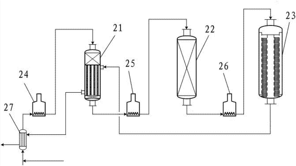
[0070] use as figure 2 The shown reaction system provided by the present invention carries out catalytic reforming reaction of naphtha. Wherein, the properties of the catalytic reforming feedstock oil are the same as those of Comparative Example 1.

[0071] Such as figure 2 As shown, the reaction system adopted in this embodiment is provided with three reactors connected in series, one of which is the combined bed reactor provided by the present invention, the catalyst type and loading are the same as those of Comparative Example 1, and the second and third reactors The reactor structure, catalyst loading type and volume remained the same as in Comparative Example 1. Among them, the ratio of the catalyst loading volume in the fixed bed section, the column tube section and the fixed bed section in the first reactor is 33:67:0. The inlet temperature of each reactor was optimized according to the characteristics of the present invention, and the specific process conditions a...

Embodiment 2

[0085] use as Figure 6 The reaction system shown carries out the catalytic reforming reaction of naphtha, wherein the properties of the catalytic reforming feed oil are the same as those of Comparative Example 1, and the product quality indicators are the same as those of Comparative Example 2. The specific process conditions are shown in Table 8. In Example 2, the temperature of the reforming feed is 80°C. After heat exchange by the heat exchanger, the temperature of the reforming feed at the entrance of the first heating furnace is 430°C, and the reactant flow of the three reverses enters the first reverse tube section The inlet temperature is 475°C. After providing heat, the temperature leaving the first-stage pipe section is 465°C. After being heated by the fourth heating furnace, it enters the fourth stage to continue the catalytic reforming reaction; the reaction outlet stream of the four-stage reaction enters the second stage pipe section. The inlet temperature of the...


PUM

PropertyMeasurementUnit
pore sizeaaaaaaaaaa

Abstract

A semi-regeneration catalytic reforming reaction system comprises at least one combined bed reactor and a fixed bed reactor connected with the combined bed reactors in series.Each combined bed reactor is formed by combination of a fixed bed and a tube nest type fixed bed catalyst bed, wherein in the tube nest type fixed bed catalyst bed, the outlet material flow of the follow-up fixed bed reactor makes indirect contact with the reaction material flow of the combined bed reactor and heat is provided.The invention further provides a catalytic reforming method adopting the system.The problem that the operation efficiency of a reforming reaction system is hard to improve due to the limitation of the regeneration period of a catalyst of a final reactor can be well solved, and the reforming reaction system is made to obtain higher operation benefits.

Description

technical field [0001] The invention relates to the field of naphtha catalytic reforming, in particular to a semi-regenerative catalytic reforming reaction system and method. Background technique [0002] Catalytic reforming is an important refinery process that converts naphtha with low octane or aromatics content into high-octane gasoline or products with high aromatics content, while producing hydrogen by-product. [0003] Since the world's first naphtha catalytic reforming unit was put into operation in 1949, this process has become one of the main processes in the oil refining industry. Although the catalytic reforming process is a very mature process, facing the challenges of continuous increase in global transportation fuel demand, surge in demand for aromatics raw materials, cheap hydrogen source for hydrogenation process development, and increasingly stringent environmental regulations and regulations, catalytic reforming process equipment has The processing volume...

Claims


Application Information

Patent Timeline
Patent Type & Authority Patents(China)
IPC IPC(8): C10G35/04
CPCC10G35/04C10G2300/1044C10G2300/305C10G2300/70C10G2400/02C10G2400/30
Inventor 石玉林
Owner 石玉林
Why Eureka
Try Eureka