
Cropping working station for PIN material strap

A strip and cutting technology, applied in cutting devices, manufacturing tools, metal processing equipment, etc., can solve the problems of fully automatic PIN strip cutting and PIN process, low production efficiency, etc., and achieve accurate PIN needle spacing. High efficiency, reduced manpower consumption, and high production efficiency

Active Publication Date: 2016-05-25
CWB AUTOMOTIVE ELECTRONICS
View PDF6 Cites 5 Cited by
  • Summary
  • Abstract
  • Description
  • Claims
  • Application Information

AI Technical Summary

Problems solved by technology

[0005] Therefore, the technical problem to be solved by the present invention is to overcome the defects that the cutting station of the PIN needle material tape in the prior art cannot realize the full automation of the PIN needle cutting and PIN process, and the production efficiency is low, thereby providing a method that can Realize the fully automatic cutting and dividing PIN process of PIN needles, and the cutting station of PIN needle strips with high production efficiency

Method used


Image

  • Cropping working station for PIN material strap
  • Cropping working station for PIN material strap
  • Cropping working station for PIN material strap

Examples


Embodiment Construction

[0070] The technical solutions of the present invention will be clearly and completely described below in conjunction with the accompanying drawings. Apparently, the described embodiments are some of the embodiments of the present invention, but not all of them. Based on the embodiments of the present invention, all other embodiments obtained by persons of ordinary skill in the art without making creative efforts belong to the protection scope of the present invention.

[0071] In the description of the present invention, it should be noted that the orientation or positional relationship indicated by the terms "center", "upper" and "lower" are based on the orientation or positional relationship shown in the drawings, and are only for the convenience of describing the present invention and simplified descriptions, rather than indicating or implying that the device or element referred to must have a specific orientation, be constructed and operate in a specific orientation, and t...


PUM


Abstract

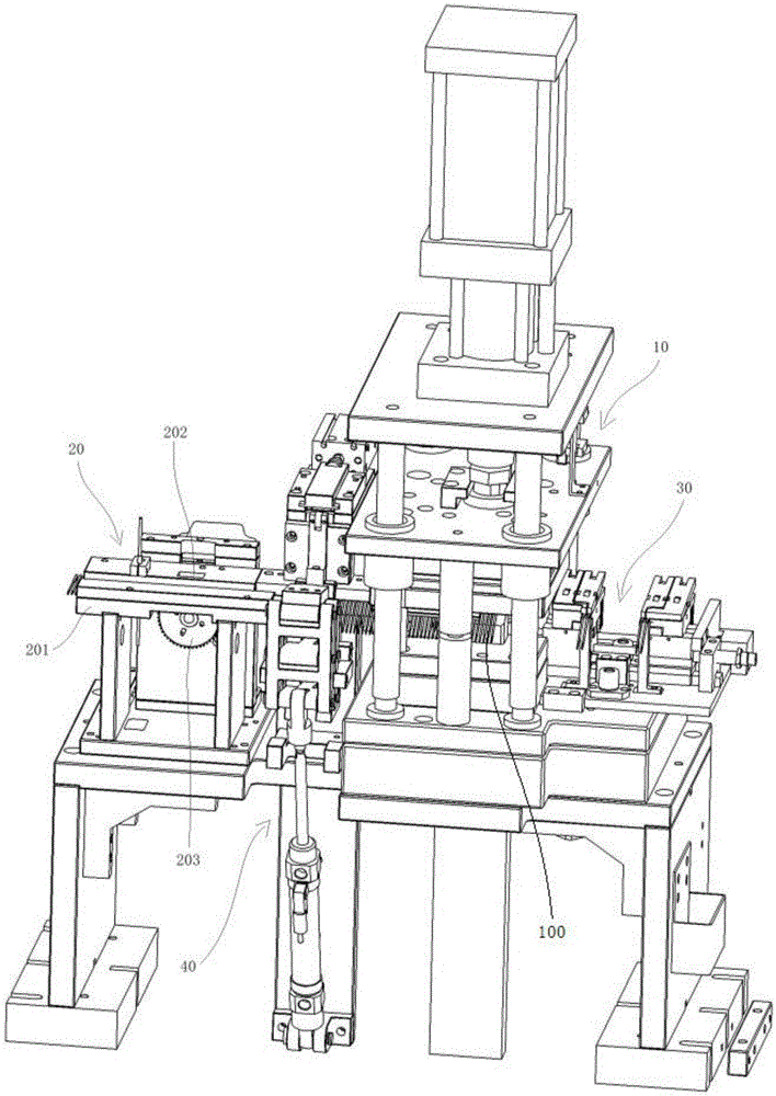
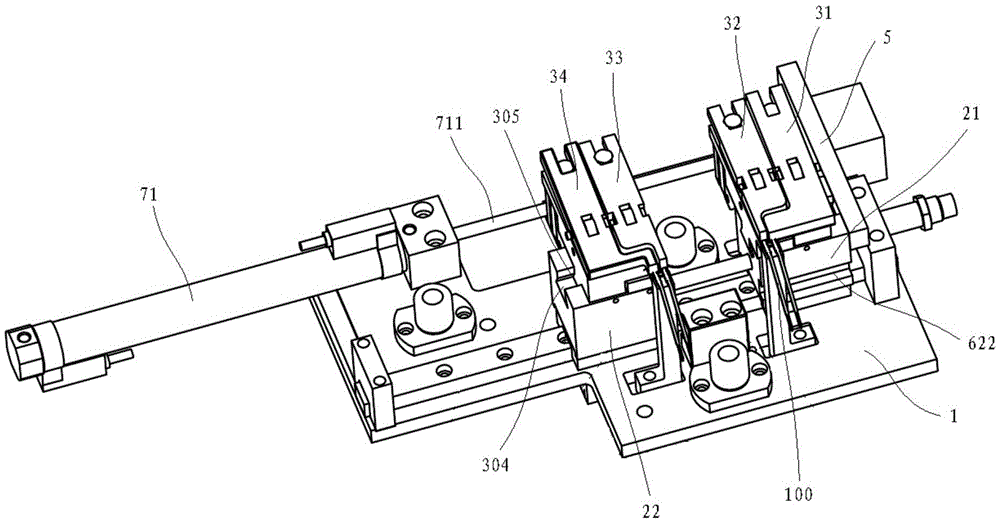
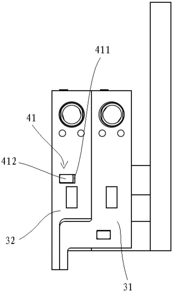
The invention provides a cropping working station for a PIN material strap. The cropping working station comprises a cropping mechanism cropping the PIN material strap into separated PINs, a feeding mechanism feeding the PIN material strap to the cropping mechanism, and a PIN distributing mechanism. The PIN distributing mechanism is used for clamping a set number of PINs from the cropping mechanism and distributing the clamped PINs so as to enable the PINs to be distributed according to preset intervals. According to the cropping working station for the PIN material strap, the PIN material strap can be cropped into the separated PINs, the set number of PINs can be distributed so that the PINs can be distributed according to the preset intervals, full automation of the PIN cropping and distributing technology can be achieved, production efficiency is high, the interval accuracy of the PINs is high, and manpower cost is reduced.

Description

technical field [0001] The invention relates to the technical field of processing equipment for electronic components, in particular to a cutting station for PIN needle strips. Background technique [0002] Electronic components, especially various electronic connectors, are usually formed by assembling an insulating base and a plurality of metal PIN pins. The assembly method of the PIN pin and the insulating base is generally plug-in or injection molding. The insertion refers to inserting the PIN needle into the preset hole of the insulating base; the injection molding refers to putting the PIN needle into the mold and directly injection molding the insulating base seamlessly fixed with the PIN needle . [0003] When the PIN needle is processed, the conductive metal material is usually first cut into a strip structure, and then the required PIN needle structure is punched out in a punching machine. For the convenience of transportation and subsequent production, some res...

Claims


Application Information

Patent Timeline
IPC IPC(8): B23D31/00B23D33/00
CPCB23D31/00B23D33/00
Inventor 张阿丰刘小兵林济富胡文状卢志强徐然盼
Owner CWB AUTOMOTIVE ELECTRONICS
Learn More