Eureka AIR delivers breakthrough ideas for toughest innovation challenges, trusted by R&D personnel around the world.

Novel composite material drilling bit and manufacturing method thereof

A composite material and manufacturing method technology, applied in twist drills and other directions, can solve the problems of fiber pullout, chipping and poor surface roughness on the surface of the hole wall, achieve reasonable drill tip angle and rake angle, and reduce axial cutting force , The effect of maintaining the sharpness of the cutting edge

Inactive Publication Date: 2016-04-06
XINAN TOOLS GUIZHOU PROV
View PDF5 Cites 12 Cited by
  • Summary
  • Abstract
  • Description
  • Claims
  • Application Information

AI Technical Summary

Problems solved by technology

[0002] Composite materials are two-phase or multi-phase structural materials made by mixing soft and viscous matrix materials with high-strength, high-hardness fiber reinforcement materials. Their anisotropy, low thermal conductivity, and low interlayer bonding strength make them It has become a typical difficult-to-machine material. Therefore, in the process of drilling composite materials with ordinary drill bits, phenomena such as material delamination, tearing and burrs at the entrance and exit, and fiber pull-out on the surface of the hole wall are prone to occur. The above phenomena make the processed hole It is difficult to guarantee the shape and position accuracy of the drill bit, and the surface roughness is poor, and the poor roughness increases the friction resistance between the drill bit and the hole wall, resulting in an increase in the temperature of the drill bit, a decrease in service life, and even chipping
Therefore, the existing drill bits are still not ideal for processing composite materials.

Method used


Image

  • Novel composite material drilling bit and manufacturing method thereof
  • Novel composite material drilling bit and manufacturing method thereof
  • Novel composite material drilling bit and manufacturing method thereof

Examples


Embodiment

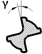
[0021] see Figure 1~3 , a new type of composite material drill bit of the present invention, including a tool holder 1 and a cutting part 2, the end of the cutting part 2 is made with a step 9, and the step 9 divides the cutting part 2 into the first chip part and the tool holder 1 connected second chip part, and the diameter of the first chip part is smaller than the diameter of the second chip part. 7. A chisel edge 4 is provided between the first main cutting edges 8, and a second main cutting edge 6 and a second auxiliary cutting edge 5 symmetrical to the axis line are arranged at the second chip part. The step 9 and the The first secondary chip edge 7 is connected to the second main chip edge 6 . The rake angle γ of the first auxiliary cutting edge 7 and the second auxiliary cutting edge 5 are the same, and both are 5°-7°. The drill point angle β of the first chip part is 120°-130°. The length B of the chisel edge 4 is 1-1.5 mm.

[0022] A method for making the above...


PUM


Abstract

The invention discloses a novel composite material drilling bit and a manufacturing method thereof. The novel composite material drilling bit comprises a cutter handle (1) and a cutting part (2). The end of the cutting part (2) is provided with a step (9). The cutting part (2) is divided into a first cutting part and a second cutting part which is connected with the cutter handle (1) through the step (9), and the diameter of the first cutting part is smaller than that of the second cutting part. First main cutting blades (8) and first auxiliary cutting blades (7) are symmetrically arranged on the first cutting part along the axis. Transverse blades (4) are arranged between the first main cutting blades (8). Second main cutting blades (6) and second auxiliary cutting blades (5) are symmetrically arranged on the second cutting part along the axis. The step (9) is connected with the first auxiliary cutting blades (7) and the second main cutting blades (6). When the drilling bit is used for machining a composite material, the service life of the drilling bit is long, and the precision and roughness of a machined hole are high.

Description

technical field [0001] The invention relates to a novel composite material drill bit and a manufacturing method thereof, belonging to the technical field of drill bit manufacturing. Background technique [0002] Composite materials are two-phase or multi-phase structural materials made by mixing soft and viscous matrix materials with high-strength, high-hardness fiber reinforcement materials. Their anisotropy, low thermal conductivity, and low interlayer bonding strength make them It has become a typical difficult-to-machine material. Therefore, in the process of drilling composite materials with ordinary drill bits, phenomena such as material delamination, tearing and burrs at the entrance and exit, and fiber pull-out on the surface of the hole wall are prone to occur. The above phenomena make the processed hole It is difficult to guarantee the shape and position accuracy of the drill bit, and the surface roughness is poor, and the poor roughness increases the frictional re...

Claims


Application Information

Patent Timeline
Patent Type & Authority Applications(China)
IPC IPC(8): B23B51/02
Inventor 杨秀章
Owner XINAN TOOLS GUIZHOU PROV
Why Eureka
Eureka Blog
Learn More