
Heating method for chute

A heating method and chute technology, applied in the field of chute heating, can solve the problems of reduced production efficiency, reduced combustion heat efficiency, increased fuel consumption, etc., to achieve improved heating speed and uniform heating, optimized installation position and angle, and improved thermal radiation coefficient Effect

Active Publication Date: 2016-03-30
爵翔(上海)能源科技有限公司
View PDF7 Cites 1 Cited by
  • Summary
  • Abstract
  • Description
  • Claims
  • Application Information

AI Technical Summary

Problems solved by technology

No matter what kind of mixed combustion, because the combustion aid used is air at normal temperature, and the air contains about 21% oxygen and 79% nitrogen and inert gases, of which 21% oxygen and 79% are really involved in the combustion reaction. Nitrogen and inert gases do not participate in the combustion reaction, but as part of the high-temperature flue gas, they take away a large amount of sensible heat, resulting in a decrease in combustion thermal efficiency and an increase in fuel consumption
In addition, this combustion method has a slow heating rate and a long heating time for the chute, which affects the production progress; the chute is heated unevenly, the temperature of the part close to the burner is high, and the temperature of the part far away from the burner is low, which is very easy to cause the melt in the chute. The bonding and residues of the chute affect the product quality (especially the pouring quality), and the residue on the chute needs to be cleaned before the next round of production can be carried out, which increases the labor intensity of the workers and reduces the production efficiency.
This combustion method also produces a large amount of smoke, smoke and fire can be seen everywhere on the chute, and the operating environment of the workers deteriorates

Method used


Image

  • Heating method for chute
  • Heating method for chute
  • Heating method for chute

Examples


Embodiment Construction

[0021] In order to make the object, technical solution and advantages of the present invention clearer, various embodiments of the present invention will be described in detail below in conjunction with the accompanying drawings. However, those of ordinary skill in the art can understand that, in each implementation manner of the present invention, many technical details are provided for readers to better understand the present application. However, even without these technical details and various changes and modifications based on the following implementation modes, the technical solution claimed in each claim of the present application can be realized.

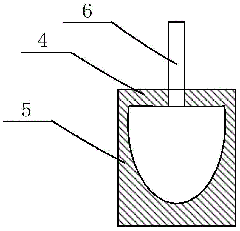
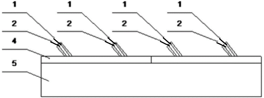
[0022] The heating method of the chute involved in the first embodiment of the present invention uses natural gas as a fuel, and an oxygen mixture with an oxygen volume concentration of 99.6% (the balance is nitrogen and an inert gas) as a combustion aid, and the above-mentioned fuel and combustion aid The agent is sent into...


PUM


Abstract

The invention relates to the field of the metallurgical industry, and discloses a heating method for a chute. According to the heating method, fuel and mixed gas containing high-concentration oxygen or oxygen-rich air serving as accelerants are fed into the chute through a combustion spraying-in assembly to be combusted in a mixed mode, and the heat generated during mixed combustion is used for achieving heating and heat preservation of the chute. According to the method, the combustion spraying-in assembly used for feeding the fuel and the accelerants into the chute comprises a group of coaxial metal sleeve pipe spraying guns and / or metal single-pipe spraying guns arranged on a chute covering plate at intervals. The heating method for the chute can greatly reduce fuel consumption, improve the heating speed and uniformity of the chute, and greatly reduce combustion smoke amount and emission of pollutants.

Description

technical field [0001] The invention belongs to the field of metallurgical industry, in particular to a method for heating a chute used in a smelting process. Background technique [0002] The chute is a conveying equipment that utilizes the height difference and the liquid's own weight to transport the liquid. etc. Generally, the upper part of the chute has a movable chute cover to reduce heat loss. [0003] The high-temperature melt (including copper glaze, blister copper, anode furnace copper water, or other high-temperature metal melt and slag) produced in copper pyrometallurgy and other metallurgical smelting processes usually passes through the chute in each smelting unit process For transportation and transition, and the chute is at ambient temperature, when the high-temperature melt passes through the chute, it will inevitably cool down and cool down, and it is easy to solidify and stick to the chute, which will affect the product quality and production efficiency, ...

Claims


Application Information

Patent Timeline
Patent Type & Authority Applications(China)
IPC IPC(8): F27D3/10
Inventor 刘枫
Owner 爵翔(上海)能源科技有限公司
Learn More