
Special automatic assembly welding machine for middle slot

A welding and automatic technology, applied in welding equipment, auxiliary welding equipment, welding/cutting auxiliary equipment, etc., can solve the problems of unguaranteed welding speed, low degree of automation, affecting production efficiency, etc., so as to reduce the labor intensity of workers and improve the The effect of welding quality and improving work efficiency

Active Publication Date: 2017-03-22
郑州市嵩阳煤机制造有限公司
View PDF5 Cites 0 Cited by
  • Summary
  • Abstract
  • Description
  • Claims
  • Application Information

AI Technical Summary

Problems solved by technology

[0005] As the load-bearing part of the material, the middle tank needs to bear the friction of coal, scraper and chain during operation. Therefore, the demand for the middle tank as a loss part is relatively large. The existing middle tank is manually welded. The stability of the seam quality and the welding speed cannot be guaranteed, which affects the production efficiency, especially the mold used for welding, which has a low degree of automation, and a special welding equipment needs to be proposed.

Method used


Image

  • Special automatic assembly welding machine for middle slot
  • Special automatic assembly welding machine for middle slot
  • Special automatic assembly welding machine for middle slot

Examples


Embodiment Construction

[0046] The technical solutions in the embodiments of the present invention will be clearly and completely described below in conjunction with the accompanying drawings in the present invention. Apparently, the described embodiments are only illustrative partial implementations of the present invention, and are not intended to limit the scope of the present invention. , any equivalent changes and modifications made by those skilled in the art without departing from the concepts and principles of the present invention shall fall within the protection scope of the present invention.

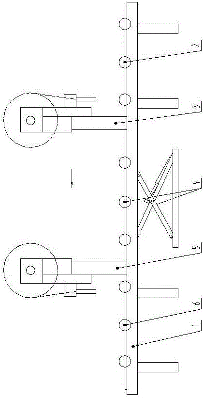
[0047] see figure 1 , in the figure (the direction of the arrow indicates the direction of travel of the middle groove), the special automatic welding machine tool for the middle groove of the present invention includes a frame 1, and the front clamping and positioning device 2, automatic Welding device I3, lifting and turning device 4, automatic welding device II5 and rear clamping and positioning ...


PUM


Abstract

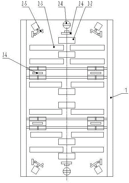
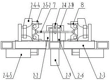
The invention belongs to the technical field of machining of a middle trough of a scraper conveyor, and particularly relates to a specialized automatic assembly welding machine tool for the middle trough. The specialized automatic assembly welding machine tool comprises a rack, wherein a front clamping location device, an automatic welding device I, a lifting turnover device, an automatic welding device II and a rear clamping location device are sequentially arranged on the upper edge of the rack in a middle trough machining moving direction; the front clamping location device comprises one column of middle plate supporting rollers, two columns of middle trough supporting rollers, a trough ledge side face clamping location mechanism, an overturn type trough ledge end ditch clamping location mechanism, a middle plate front and back clamping location mechanism and a middle plate top pressing mechanism; and the automatic welding device I / II comprise welding supports arranged along the two sides of the rack, welding guns, wire feeders, welding wire winding drums, welding support longitudinal moving mechanisms, welding gun and wire feeder lifting moving mechanisms, welding gun and wire feeder transverse moving mechanisms and welding wire winding drum lifting supporting mechanisms. The specialized automatic assembly welding machine tool can improve working performance and welding quality and reduces labor intensity of workers.

Description

technical field [0001] The invention belongs to the technical field of processing the middle groove of scraper conveyors, in particular to a special automatic welding machine tool for the middle groove. Background technique [0002] The main structure and components of various types of scraper conveyors are basically the same. It is mainly composed of three parts: the head, the middle and the tail. [0003] The working principle of the scraper conveyor is that the open conveying trough in the middle is used as the coal receiving part, and the scraper is fixed on the chain to form a scraper chain, which is used as a traction member. When the transmission part of the machine head is started, it drives the sprocket on the machine head shaft to rotate, so that the scraper chain circulates and drives the coal to move along the conveying trough until it is unloaded at the machine head. The scraper chain circulates around the sprocket to complete the coal transportation. [0004]...

Claims


Application Information

Patent Timeline
Patent Type & Authority Patents(China)
IPC IPC(8): B23K37/00B23K37/04B23K37/047
CPCB23K37/00B23K37/0443B23K37/047
Inventor 弋现生李延朝李怀永贺小克
Owner 郑州市嵩阳煤机制造有限公司
Learn More