
Single-stage non-isolated double cuk type inverter without electrolytic capacitor

An electrolytic capacitor, non-isolated technology, applied to electrical components, AC power input conversion to DC power output, output power conversion devices, etc., can solve the problem of poor reliability, large volume of electrolytic capacitors, low power density of inverters, etc. problem, achieve the effect of reducing EMI and simple control scheme

Active Publication Date: 2017-11-24
YANSHAN UNIV
View PDF6 Cites 0 Cited by
  • Summary
  • Abstract
  • Description
  • Claims
  • Application Information

AI Technical Summary

Problems solved by technology

The other is an isolation solution, that is, adding a step-up transformer to the inverter to increase the voltage level and achieve electrical isolation, but the addition of the transformer will also increase the system cost and volume and affect the overall conversion efficiency
Obviously, the single-stage non-isolated scheme that can directly realize buck-boost is more in line with the needs of new energy and renewable energy power generation technologies, but large-capacity inverters are used in existing single-stage non-isolated buck-boost inverters. Electrolytic capacitors are used for energy storage. Due to the large size and short life of electrolytic capacitors, the power density of the inverter is low and the reliability of work is poor. Electrolytic capacitors become the key to limit the service life of the inverter. The future development trend of the transformer

Method used


Image

  • Single-stage non-isolated double cuk type inverter without electrolytic capacitor
  • Single-stage non-isolated double cuk type inverter without electrolytic capacitor
  • Single-stage non-isolated double cuk type inverter without electrolytic capacitor

Examples


Embodiment Construction

[0059] Below in conjunction with accompanying drawing and specific embodiment the present invention is described in further detail:

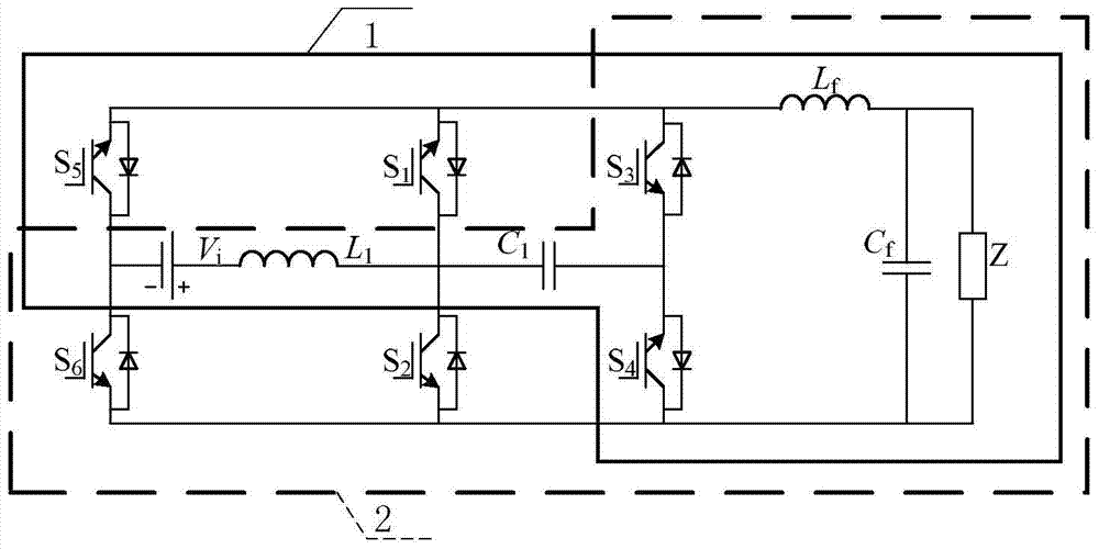
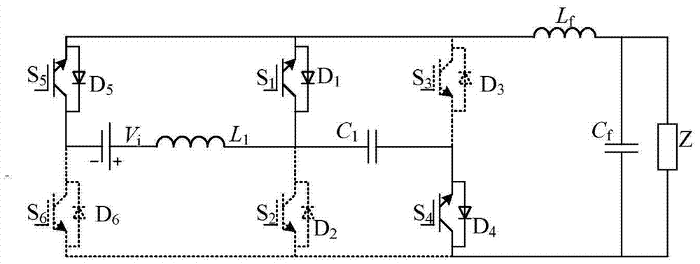
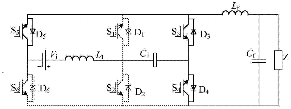
[0060] Such as figure 1 Shown, a kind of single-stage non-isolation electrolytic capacitor double Cuk type inverter of the present invention, its embodiment comprises the first Cuk circuit 1 and the second Cuk circuit 2;

[0061] In the first Cuk circuit 1, the fifth power switch tube S 5 The collector is connected to the negative pole of the input power supply, and its emitter is connected to the first power switch tube S at the same time. 1 emitter, the third power switch S 3 collector and filter inductance L f One end; the positive pole of the input power supply is connected to the input inductor L 1 One end of the input inductance L 1 The other end is connected to the first power switch tube S 1 collector as well as the input capacitor C 1 One end of the input capacitor C 1 The other end is connected to the third power switch tube S...


PUM


Abstract

The present invention discloses a single-stage non-isolated double-Cuk type inverter without an electrolytic capacitor. An anode of an input power supply is connected to one end of an input inductor, a cathode of the input power supply is connected to a collector of a fifth power switch tube and a collector of a sixth power switch tube of a second Cuk circuit, and the other end of the input inductor is connected to a collector of a first power switch tube, and a collector of a second power switch tube and one end of an input capacitor; the other end of the input capacitor is connected to an emitter of a fourth power switch tube and an emitter of a third power switch tube; and an emitter of the fifth power switch tube is connected to an emitter of the first power switch tube, a collector of the third power switch tube and one end of a filter inductor, the other end of the filter inductor is connected to one end of the filter capacitor and one end of a load, the other ends of the filter capacitor and the load are connected to an emitter of the sixth power switch tube, an emitter of the second power switch tube and a collector of the fourth power switch tube. The single-stage non-isolated double-Cuk type inverter disclosed by the present invention is simple in structure, quick in dynamic response and good in tracking performance, and has relatively strong inhibiting capacity for fluctuations of the power supply and the load.

Description

technical field [0001] The invention relates to an electric energy conversion device, in particular to a single-stage non-isolated double-Cuk type inverter without electrolytic capacitors, which is suitable for single-phase inverter applications and can realize both voltage boost and voltage drop. Background technique [0002] Energy is the material basis for the survival and development of human beings. The limitation of fossil energy and a large number of exploitation and utilization have led to increasingly serious problems of energy shortage and environmental degradation. New energy and renewable energy are getting more and more attention due to their characteristics of large quantity, cleanness and safety, and inverter is a key link in new energy and renewable energy power generation technology. Compared with traditional power generation technologies, the output power of new energy and renewable energy power generation devices has volatility and randomness. For example,...

Claims


Application Information

Patent Timeline
Patent Type & Authority Patents(China)
IPC IPC(8): H02M7/797
CPCH02M7/797
Inventor 王立乔薛金柱
Owner YANSHAN UNIV
Learn More