
A detection method for out-of-round center hole of shaft parts

A technology of shaft parts and detection method, applied in the field of shaft parts, can solve problems such as inability to obtain quantitative and accurate measurement, and achieve the effect of improving results, simple measurement tools, and eliminating human factors

Active Publication Date: 2018-04-03
桂林福达曲轴有限公司
View PDF7 Cites 0 Cited by
  • Summary
  • Abstract
  • Description
  • Claims
  • Application Information

AI Technical Summary

Problems solved by technology

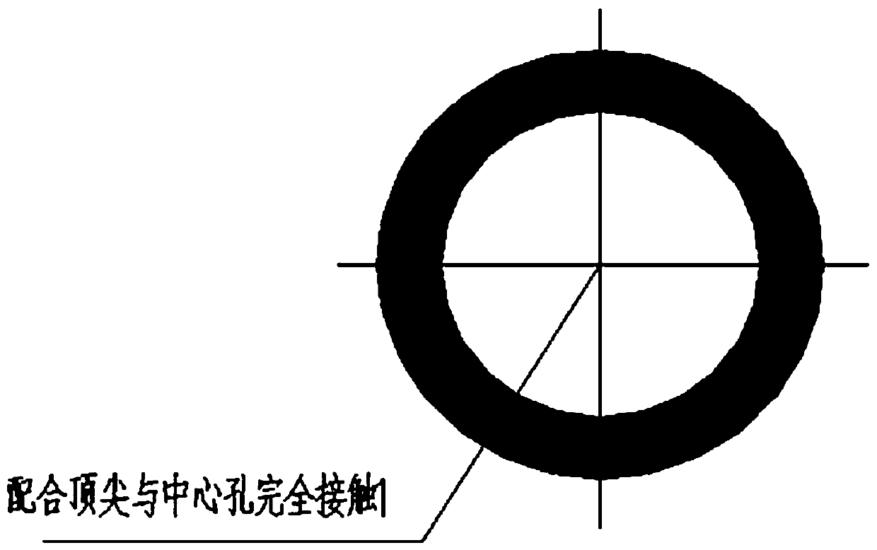
However, there is still no reliable and quantitative detection method for the detection and control of the out-of-roundness of the 60-degree conical surface of the central hole. Usually, after applying red powder on the matching tip, it is ground and contacted with the central hole of the workpiece. Take a rough look at the contact situation. This method has a lot to do with the amount of red lead powder applied, the degree of dilution and the force of the operator, and quantitative and accurate measurements cannot be obtained.

Method used


Image

  • A detection method for out-of-round center hole of shaft parts
  • A detection method for out-of-round center hole of shaft parts
  • A detection method for out-of-round center hole of shaft parts

Examples


Embodiment Construction

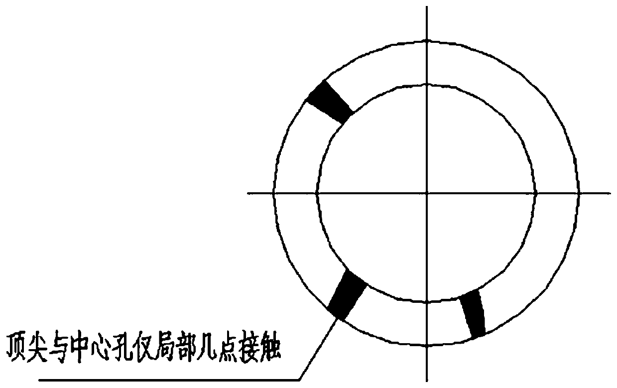
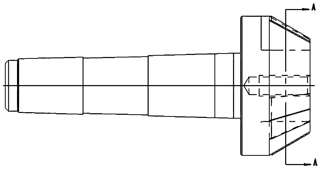
[0034] First, a top spare part of a machine tool that fits with the center hole of the workpiece is remade through tool grinding or wire cutting, and it is remade into a three-point top for testing (see Figure 4 with Figure 5 ), the top retains only three contact parts, the width is 2~3mm, and the distribution is about 120 degrees; after removing the full-shaped headstock top of the normal grinding workpiece, install the top on the machine tool for grinding the workpiece, such as Image 6 , to form the three-point center point 1 of the head frame, and then hoist the workpiece 2 with the out-of-round center hole to be inspected to the machine tool for clamping. The dead center 3 of the frame cooperates, and the dead center 3 of the tailstock plays the role of support and positioning. Use a marker pen to mark on the three-point center 1 of the head frame and the workpiece 2 respectively (such as Figure 7 The black dot in ●), then jog the button of the machine tool, and the s...


PUM


Abstract

The invention discloses a center hole out-of-roundness detection method of shaft parts. The method includes the following steps that a spare tip of a machine tool is transformed into a three-point tip for detection; the three-point tip is arranged on a machine tool headstock for grinding a workpiece to form a headstock three-point tip; the workpiece to be subjected to center hole out-of-roundness detection is hoisted to the machine tool to be clamped and the headstock three-point type tip and the workpiece are marked with marks through a marking pen; a machine tool button is jogged, a heart-shaped clamping and poking rod of the machine tool drives the workpiece to jog and rotate; the runout value A1 of the portion closest to the shaft neck of the headstock three-point type tip is measured; the steps mentioned above are repeated, then the machine tool button is jogged again to stop the workpiece from rotating, the workpiece is poked manually to rotate clockwise by about 90 degrees, 180 degrees and 270 degrees, and the runout value A2, the runout value A3 and the runout value A4 are recorded; and the Amax-Amin difference value serves as the center hole out-of-roundness judgment value. By the adoption of the center hole out-of-roundness detection method, the precise detection purpose of center hole out-of-roundness of the shaft parts can be well achieved, and the clear and operable control requirements can be met for control over center hole out-of-roundness.

Description

technical field [0001] The invention relates to shaft parts, in particular to a detection method for out-of-round center holes of shaft parts. Background technique [0002] Usually, the final finishing of shaft parts requires grinding to ensure the dimensional accuracy and shape tolerance of the journal (such as the roundness and cylindricity of the journal, etc.). The positioning reference of the grinding process is generally the center hole at both ends of the shaft part. , The machining accuracy of the center hole will directly affect the accuracy of the machined parts. According to the existing processing equipment, center hole processing is generally divided into two situations: one is that the shaft parts do not move, and the tool rotates to process the center hole; the other is that the shaft parts rotate, the tool does not move, In this case, a center frame needs to be used to support the workpiece journal. The tools used in the above two processing methods are cent...

Claims


Application Information

Patent Timeline
Patent Type & Authority Patents(China)
IPC IPC(8): B24B41/06B24B5/04B24B5/36B24B49/04G01B5/20
CPCB24B5/04B24B5/363B24B41/062B24B49/04G01B5/201
Inventor 张淑琪
Owner 桂林福达曲轴有限公司
Learn More