
Capacitor module and manufacturing method thereof

A technology for capacitors and shells, which is applied in the field of capacitor modules and its manufacturing, which can solve problems such as hindering weight reduction, achieve the effects of reducing load, maintaining capacitor performance, and preventing deterioration of sealing strength

Active Publication Date: 2018-09-11
NIPPON CHIMI CON CORP
View PDF8 Cites 0 Cited by
  • Summary
  • Abstract
  • Description
  • Claims
  • Application Information

AI Technical Summary

Problems solved by technology

On the other hand, regarding the capacitor module, insulation and weight reduction are required, but in the case of filling with insulating resin, although the fixing strength and insulation are improved, it hinders weight reduction

Method used


Image

  • Capacitor module and manufacturing method thereof
  • Capacitor module and manufacturing method thereof
  • Capacitor module and manufacturing method thereof

Examples


no. 1 Embodiment approach

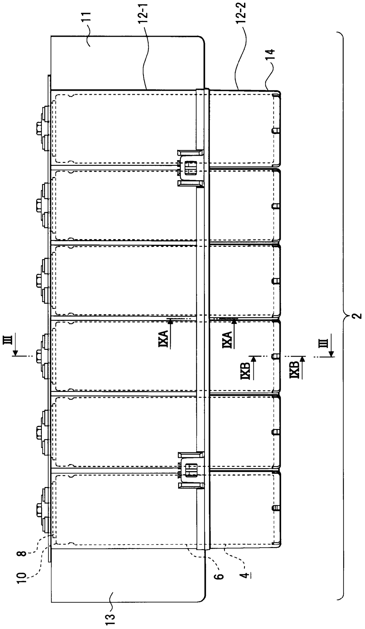
[0047] figure 1 A configuration example of the capacitor module of the first embodiment is shown. The capacitor module 2 includes a plurality of capacitors 4 . In this embodiment, six capacitors 4 are used, but the number may be six or less or six or more. For each capacitor 4, for example, an electric double layer capacitor or an electrolytic capacitor is used.

[0048]Each capacitor 4 has a case 6 in which a capacitor element is accommodated. The housing 6 is molded from aluminum, for example. The casing 6 is sealed by a sealing plate 8 . The sealing plate 8 is formed of an insulating plate such as an insulating synthetic resin, and an anode terminal, a cathode terminal, and an auxiliary terminal are formed as external terminals on the sealing plate 8 . The anode terminal, the cathode terminal, and the auxiliary terminal are integrally attached to the sealing plate 8 by insert molding when the sealing plate 8 is formed. The anode terminal is connected to the anode of t...

no. 2 Embodiment approach

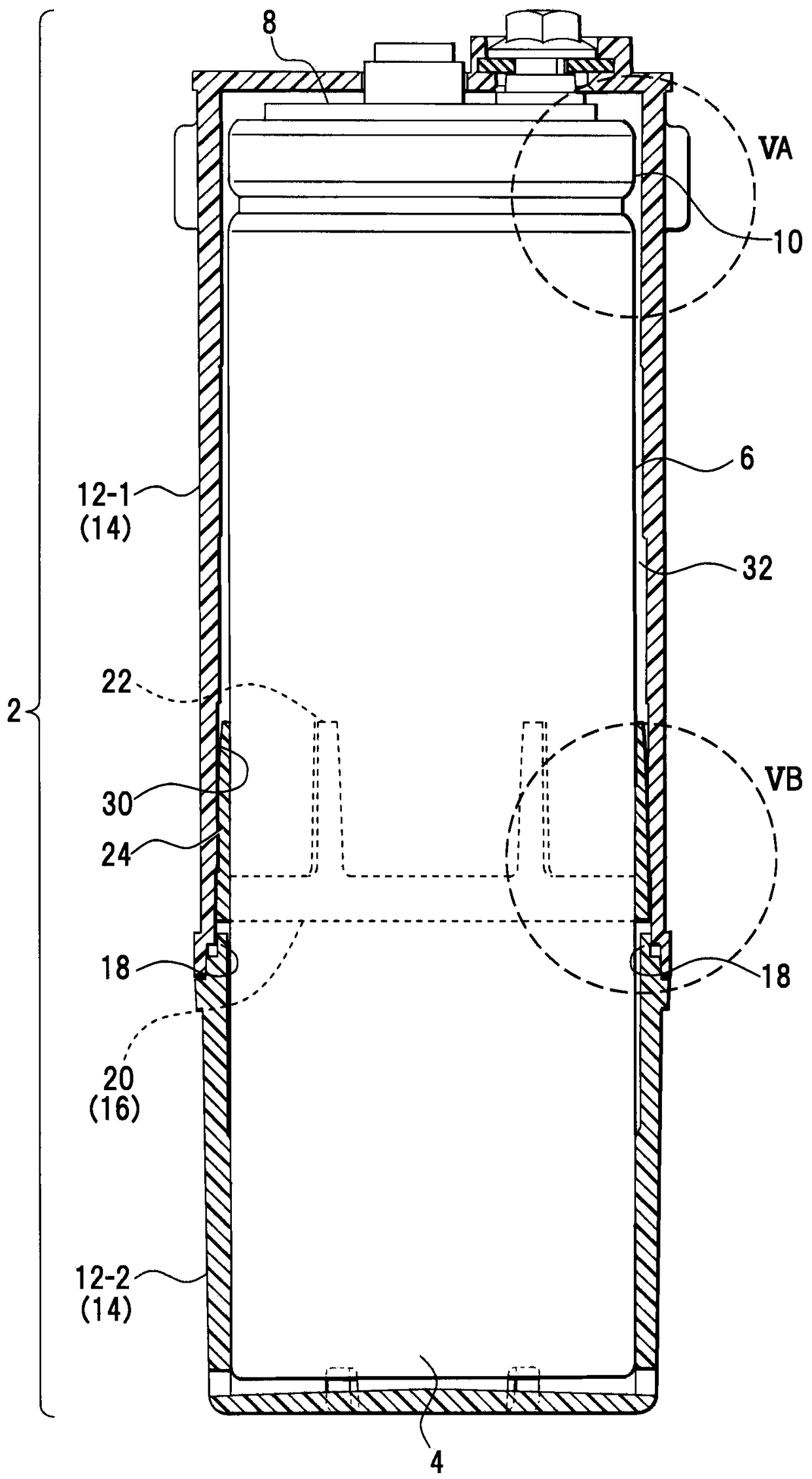
[0084] Next, a configuration example of the main case 12-1 and the bottom case 12-2 that accommodate a plurality of capacitors will be described. When the capacitor module 2 is installed in, for example, a motor vehicle, it is installed outside the cabin and exposed to the outside air. Therefore, there is a possibility that water droplets may adhere to or accumulate on the capacitor module 2 due to dew condensation or the like. Even if water droplets adhere to the case member, the water droplets do not degrade the capacitor 4 . However, the adhered water droplets may corrode the resin constituting the case member.

[0085] In addition, in the capacitor module 2 of the present disclosure, for example, since the housing portion 14 is not filled with resin or the like, there is a possibility that water droplets generated by dew condensation etc. adhering to the outer surface of the capacitor 4 may intrude into the main case 12-1. And bottom shell 12-2 and accumulate. Therefore...


PUM


Abstract

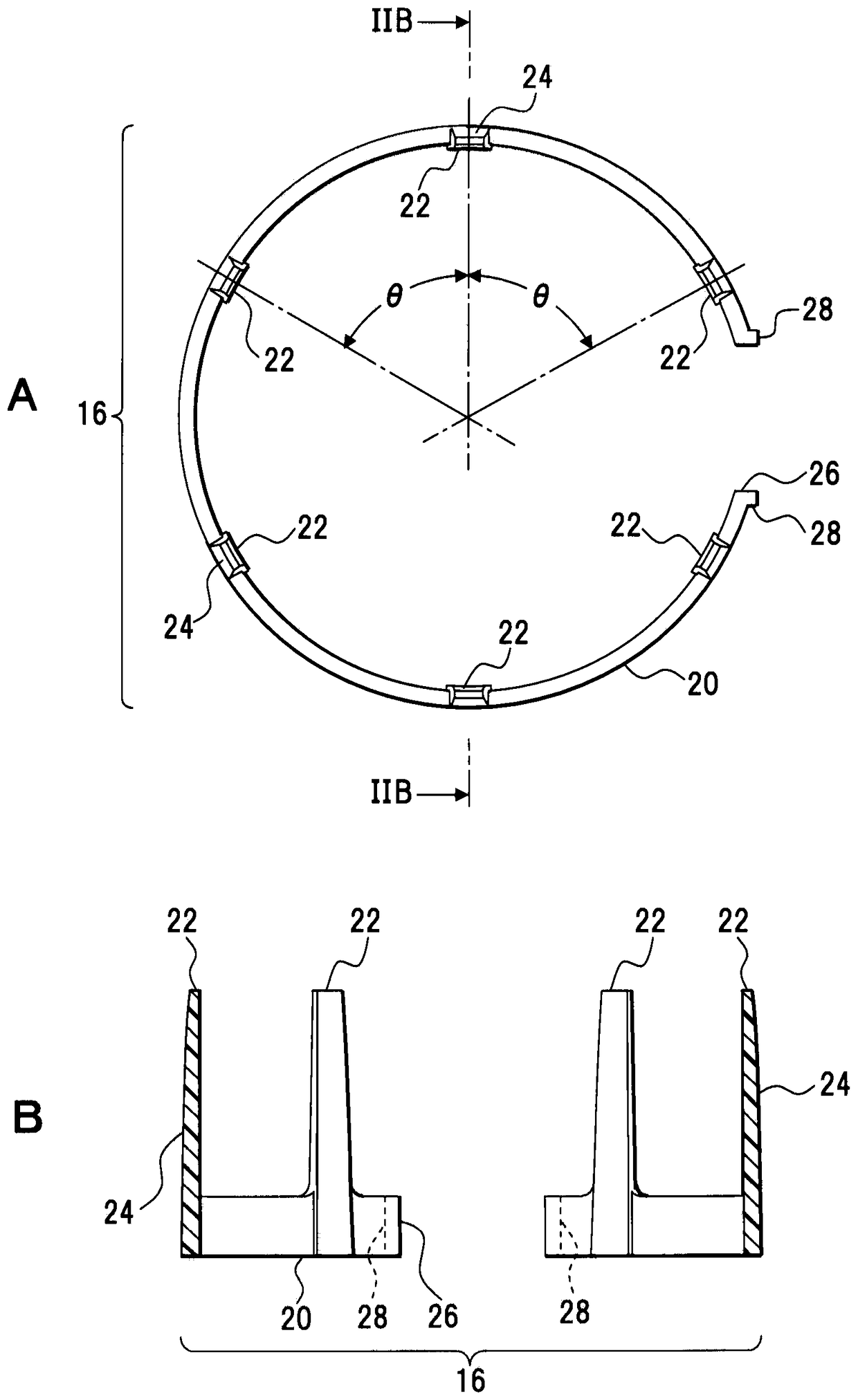
A capacitor module (2) including a case member having accommodating portions (14) that accommodate plural capacitors (4). A space (32) is included between an inner wall portion of the accommodating portions and the capacitor. A fixing member (16) is disposed in the space. The fixing member includes an annular portion (20) that surrounds a circumferential portion of the capacitor, and a wedge portion (22) that is formed on the annular portion in a direction of intersection with the annular portion. Any stress applied from the case member to the fixing member and a sealing curling portion can thereby be avoided. In addition, any load applied by vibrations to external terminals and an auxiliary terminal can be reduced, and the connection property and the fixing strength can be maintained.

Description

technical field [0001] The technology disclosed herein relates to a capacitor module having a plurality of capacitors and a method of manufacturing the same. Background technique [0002] Capacitors are used to store electrical energy in equipment such as motor vehicles that use electrical energy for driving or braking. Because capacitors are superior in rapid charge and discharge characteristics, they are suitable for equipment such as motor vehicles that require rapid starting or braking. [0003] In order to cope with the electric power required for starting or braking on the mounted equipment side, when capacitors are required to have a larger capacity, the required capacity and high voltage can be achieved by using multiple capacitors. In this case, a capacitor module in which a plurality of capacitors are assembled can be used. [0004] In such a capacitor module, it is known to cover a plurality of capacitors with a case member (for example, Patent Document 1). In ...

Claims


Application Information

Patent Timeline
Patent Type & Authority Patents(China)
IPC IPC(8): H01G2/02H01G2/04H01G9/08H01G9/26
CPCH01G2/04H01G9/08H01G9/26H01G11/10H01G11/82Y02T10/70
Inventor 一仓修
Owner NIPPON CHIMI CON CORP
Learn More