
Manufacturing method of steel structure box girder/column

A manufacturing method and box girder technology, applied in manufacturing tools, arc welding equipment, welding equipment, etc., can solve the problems of increasing product manufacturing costs, low production efficiency, delaying construction period, etc., and achieve cost saving, high production efficiency and low cost Reduced effect

Inactive Publication Date: 2016-02-17
QINGDAO BAIJIANCHENG ENVIRONMENTAL PROTECTION TECH CO LTD
View PDF0 Cites 8 Cited by
  • Summary
  • Abstract
  • Description
  • Claims
  • Application Information

AI Technical Summary

Problems solved by technology

Since electroslag welding needs to be surrounded by two baffles, partitions and the four side walls of the box-shaped beam / column to form a sleeve shape, and the clearance requirements for the sleeve are very strict, and two thicker baffles are required , also requires low production efficiency and expensive electroslag welding equipment and special nozzles, which is easy to delay the construction period, not only increases the manufacturing cost of the product, but also is difficult, making the production efficiency low
In addition, when the thickness of the wall plate of the beam and column is below 18mm, it is not easy to weld with the current electroslag welding

Method used


Image

  • Manufacturing method of steel structure box girder/column
  • Manufacturing method of steel structure box girder/column
  • Manufacturing method of steel structure box girder/column

Examples


Embodiment Construction

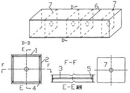
[0021] Among them, the clapboard assembly is to add the liner to the clapboard after cutting the groove. figure 2 parts shown.

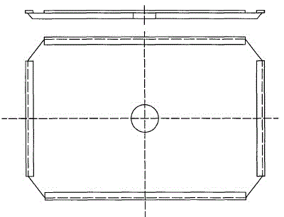
[0022] The web assembly is to add the liner to the web after cutting the groove. image 3 parts shown.

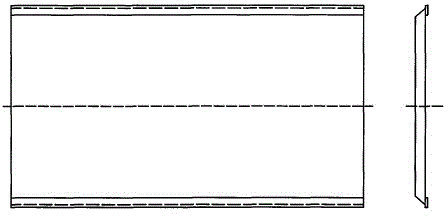
[0023] The segmental splicing of the cover plate is to disconnect the cover plate at 200mm from the first set of dividers when there is a certain distance between the divider group and the next set, so as to facilitate the welding of the divider. The joint processing such as Figure 4 shown.

[0024] The manufacturing method of steel structure box beam / column of the present invention is as Figure 5 As shown, its specific production process is as follows:

[0025] (1) Use the computer to control the size of the cover plate, web plate and its lining plate, partition plate and its lining plate for blanking, and at the same time make grooves on both sides of the web plate and four sides of the partition plate. center drilling;

[0026] (2) As...


PUM


Abstract

The invention relates to a steel structure box girder / column. A method comprises the following steps that firstly, numerical control webs and partition plates are blanked according to the size, and grooves are machined; secondly, liner plates are assembled on the back faces of the grooves of the webs and the back faces of the grooves of the partition plates in a spot welding manner; thirdly, a U shape is formed by one cover plate and two webs on a box assembling machine; fourthly, the partition plates are placed in the formed U-shaped groove, and the three edges of the partition plates are welded; and fifthly, the cover plate is arranged, and connecting welding lines of the cover plate are welded. According to the method, the problem that the box girder and column cannot be produced due to the fact that no special electroslag welding device exists is solved, and more importantly, the problem that when a multi-layer house is built, the thickness of wall plates of the girder and the column is lower than 18 mm, and welding is not easy through electroslag welding is solved. By means of the method, the machining procedure is simplified, the quality of components and the manufacturing efficiency are greatly improved, and the steel structure box girder / column has very high economic value and social value, and is easy to apply and popularize.

Description

technical field [0001] The invention relates to a method for manufacturing a steel structure box beam / column, belonging to the technical field of steel structure manufacture. Background technique [0002] As we all know, the existing steel structure box girder / column is composed of two cover plates and two web plates, and the four main welds at the junction of the four plates are designed to be full penetration grooves (CP) in sections according to the strength requirements. and partial penetration groove (PP). Among them, the steel structure box girder / column is equipped with a diaphragm, the main diaphragm and the web adopt full penetration welding, and the ordinary diaphragm and the cover web welded on three sides. [0003] At present, the manufacturing process of steel structure box girders / columns is roughly as follows: Firstly, the column plate is cut with a CNC flame cutting machine, the cover plate, web plate, partition plate and baffle plate are cut, and the web pl...

Claims


Application Information

Patent Timeline
IPC IPC(8): B23P15/00B23K9/16B23K9/18
Inventor 张栋
Owner QINGDAO BAIJIANCHENG ENVIRONMENTAL PROTECTION TECH CO LTD
Learn More