
Probe system multi-filed loading device

A technology of loading devices and probes, applied in the directions of measuring devices, instruments, scientific instruments, etc., can solve the problems of easy mutual influence, damage to electronic components, affecting the reliability, accuracy and precision of test results, and achieve reliable test results. , The effect of strong anti-interference ability of external environment

Active Publication Date: 2016-02-03
PEKING UNIV
View PDF8 Cites 8 Cited by
  • Summary
  • Abstract
  • Description
  • Claims
  • Application Information

AI Technical Summary

Problems solved by technology

However, the current testing of materials using probe systems is mostly carried out in an open test environment. The probes and test samples are directly placed in the air environment for testing, which makes it easier to load light fields, electric fields, magnetic fields, force fields and strains. field, but it is impossible to test in humidity conditions, vacuum environment, etc., and it is easily disturbed by the external environment, which affects the reliability, accuracy and precision of the test results
When other probe systems are tested in a closed environment, although vacuum and humidity control can be achieved, multiple physical fields such as electricity, magnetism, heat, force, and light cannot be simultaneously loaded: if the entire probe system and the test The materials are placed in a closed environment together, and the electric field, magnetic field, and thermal field will damage the electronic components in the probe system, which greatly limits the loading parameters such as physical field strength and frequency; if only the probe and the test material are placed in a closed environment In the process, it is difficult for the probe system to load the force field and the strain field. At the same time, the electric field, magnetic field, thermal field, force field, and light field will interfere with each other, and it is easy to affect each other during the test process, resulting in unreliable test results and insufficient accuracy.

Method used


Image

  • Probe system multi-filed loading device

Examples


Embodiment Construction

[0021] Below in conjunction with accompanying drawing, further describe the present invention through embodiment, but do not limit the scope of the present invention in any way.

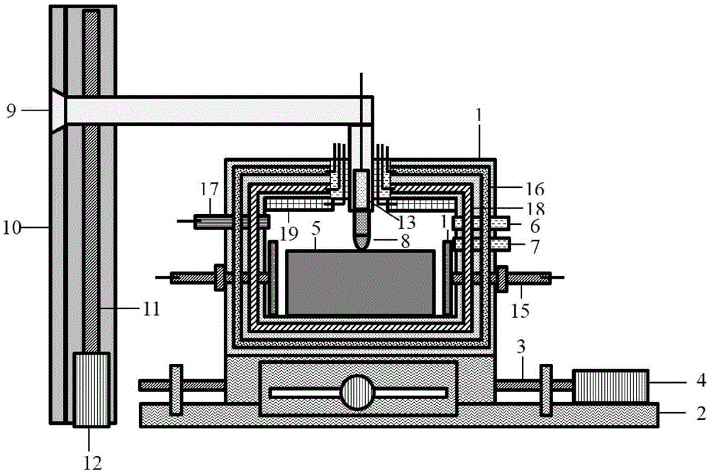
[0022] The present invention provides a probe system multi-field loading device, in the embodiment of the present invention, such as figure 1 As shown, the multi-field loading device includes a multi-field loading box 1, a horizontal moving table 2, a transmission shaft 3, a servo motor 4 that drives the transmission shaft 3 to rotate, an exhaust pipe 6 connected to an external vacuum pump, and an exhaust pipe connected to an external humidity controller 7. Probe 8, cantilever rod 9, fixed bracket 10 with slide rail, transmission shaft 11, servo motor 12 that drives transmission shaft 11 to rotate, force sensor 13, electrode 14, threaded screw rod 15, annular heating rod 16, Temperature sensor 17, circular iron rod 18 and LED flat panel lamp 19 of annular winding copper wire; The material of a plural...


PUM


Abstract

The invention discloses a probe system multi-filed loading device, which comprises a multi-field loading box, a horizontal mobile platform, a cantilever rod, a fixed support with a slide rail, a transmission shaft, a servo motor, a probe and a force sensor, wherein the multi-field loading box is fixed on the horizontal mobile platform, a sample is fixed on a box bottom, a perform hole is sealed through a sealing rubber ring, the top portion of the probe is contacted with the sample, the bottom portion of the probe is connected with the force sensor, the force sensor is arranged in the front end of the cantilever rod, and is not contacted with the sealing rubber ring, the servo motor drives the transmission shaft to rotatably control the probe to vertically move, and achieves to load a force filed and a deformation field, the outer portion of the servo motor can be connected with a vacuum pump and a humidity controller, and a box body is embedded into a ring-shaped heating bar and an iron bar which twines a copper wire, is used to load a heating field and a magnetic filed, and loads an optical field through a panel. The probe system multi-filed loading device can supply load of vacuum degree, humidity, the force field, the deformation filed, an electric field, the heating field, the magnetic filed and the optical field, and is strong in anti-jamming ability and reliable and accurate in test result.

Description

technical field [0001] The invention relates to material measuring and testing equipment, in particular to a multi-field loading device for a probe testing system. Background technique [0002] In recent years, material science and technology have developed rapidly. Optical, electrical, magnetic, thermal, biochemical and other treatment processes enable materials to have excellent electrical, magnetic, optical, thermal, acoustic, mechanical, chemical, biological functions and mutual transformation. Functional materials have greatly promoted the development and application of functional materials. Functional materials such as conductive polymers, piezoelectric ceramics, optical fibers, optoelectronics, thermoelectrics, and magnetoelectrics have been widely used in electronic information, energy transportation, biomedicine, aerospace, Instrumentation and many other fields. [0003] The working environment of functional materials is more complicated than that of ordinary mater...

Claims


Application Information

Patent Timeline
IPC IPC(8): G01N33/00
Inventor 张杨飞张兰英
Owner PEKING UNIV
Learn More