A multi-index detection microfluidic chip for quantitative shunting

A microfluidic chip and quantitative shunting technology, which is applied to laboratory containers, laboratory utensils, chemical instruments and methods, etc., can solve the problems of accurate analysis of adverse reaction results, efficient adverse reactions, sample waste and pollution, etc. , to achieve the effects of accurate analysis, simple structure, and convenient waste liquid treatment

Active Publication Date: 2017-07-25
GETEIN BIOTECH
View PDF5 Cites 0 Cited by
  • Summary
  • Abstract
  • Description
  • Claims
  • Application Information

AI Technical Summary

Problems solved by technology

Although the chip can inject enough samples into the reaction cells of the same size connected in series and then use micro-valve isolation to realize that each reaction cell is filled with the same amount of sample, but the interference between the reaction cells caused by the continuous flow of the sample causes The amount of samples participating in the reaction in the reaction pools at different positions will cause large errors, which will also cause doping and pollution between the reactions, which is not conducive to the accurate analysis of the reaction results.
[0005] Invention patent US20150093760 discloses a multi-channel structure that can divide samples into multiple detection reaction chambers. It is equipped with a sample inlet connected to multiple fluid channels, and each fluid channel is connected to a same-sized chamber for index detection reactions to occur. Circular reaction chamber, the reaction chamber is fixed with reagents for index detection. In the structure of the invention, the distances between the multiple liquid channels connected to the sample inlet and the sample inlet are different, and the sample is affected by the microchannel structure during the flow process. Due to the influence of size effect and wall slip effect, each reaction chamber cannot be filled with samples at the same time, resulting in different amounts of samples participating in the reaction in each reaction chamber during detection, which affects the accurate analysis of detection results. It is necessary to ensure that each reaction chamber If the inside is full of samples, the total sample volume must be controlled to achieve excess and sufficient injection time, which is not conducive to efficient reaction and is likely to cause sample waste and pollution

Method used


Image

  • A multi-index detection microfluidic chip for quantitative shunting
  • A multi-index detection microfluidic chip for quantitative shunting
  • A multi-index detection microfluidic chip for quantitative shunting

Examples


Embodiment 1

[0025] Embodiment 1: Multi-index microfluidic chip structure

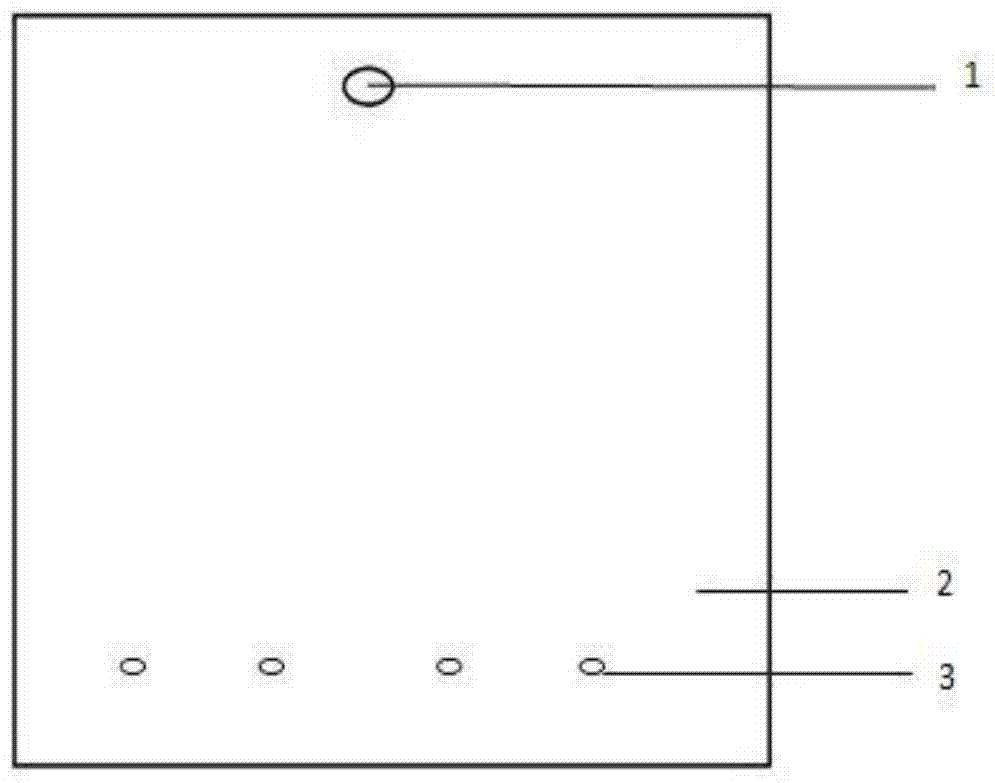
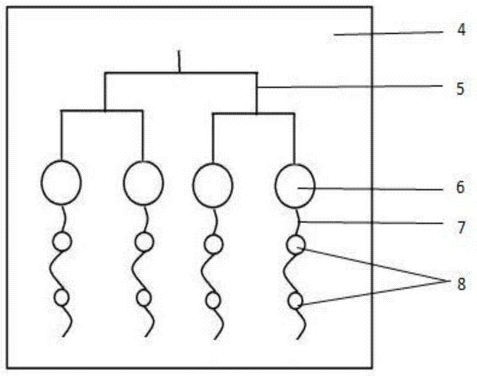
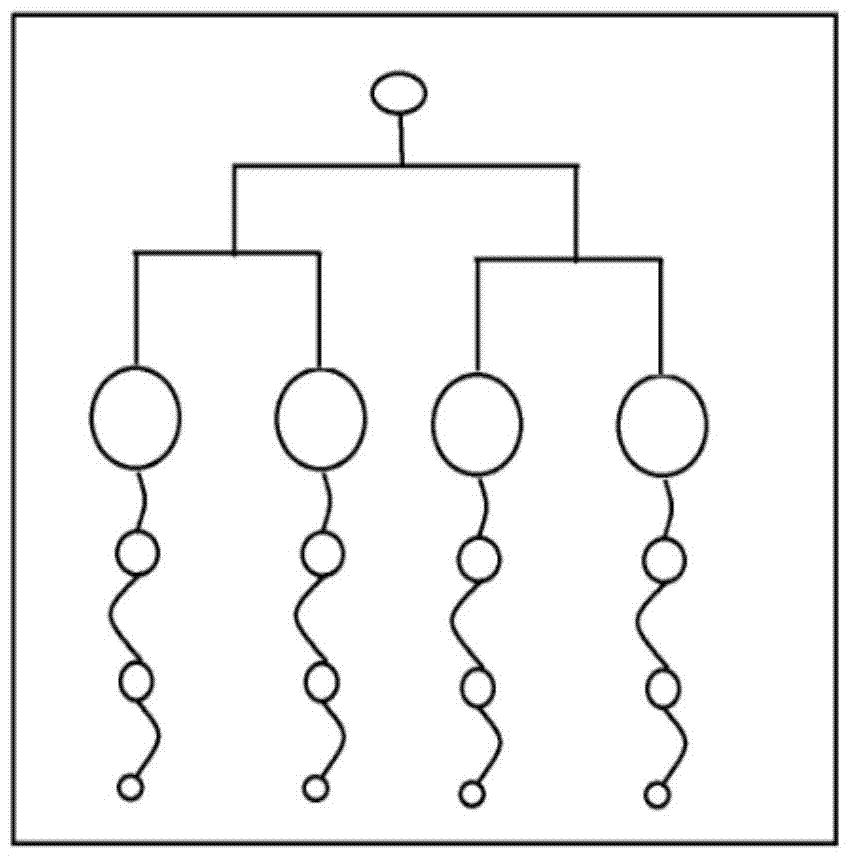
[0026] Such as figure 1 , 2 As shown in , 3, a splitting device used for the detection of four indicators can accurately quantify the amount of samples split into the four reaction chambers. The splitting device is formed by bonding the upper cover sheet 2 and the lower substrate 4 flakes. The upper cover sheet 2 is provided with a sample inlet 1, and the lower substrate 4 is provided with a multi-stage branch branch 5 connected with the sample inlet, and each branch 5 is connected with one end of a corresponding parallel reaction chamber 6, The parallel reaction chambers 6 have the same size, and the other end of the parallel reaction chamber communicates with a plurality of buffer pools 8 through an arc-shaped liquid buffer channel 7. The buffer pools 8 are connected in series, and the size decreases sequentially with the direction of liquid flow. The liquid buffer channels The 7 end communicates with the air ...

Embodiment 2

[0035] Example 2: Preparation method of microfluidic chip

[0036] Step 1: Use computer-aided design software to design the microchannel and microstructure of the shunt device chip, use a high-resolution printer to print the drawn chip structure diagram on the SU-8 glue as a mask, and use standard photolithography to make it Mold, obtain the SU-8 positive mold with the upper cover sheet of the flow splitting device and the microchannel and microstructure of the lower substrate.

[0037]Step 2: Mix the PDMS prepolymer and curing agent according to the mass ratio of 10:1, pump air in a vacuum drying oven, pour it on the surface of the mold obtained in step 1, take it out after baking at 80°C for 1 hour, and slowly remove the PDMS after cooling Peel off the mold, and use a special punching tool to drill out the sample inlet and gas outlet at the corresponding positions.

[0038] Step 3: Put the upper cover sheet and the lower substrate cut into a suitable size into a plasma clea...

Embodiment 3

[0039] Example 3: Microfluidic Chip Workflow

[0040] The sample solution that needs to be split is injected from the sample inlet 1, and the sample solution flows through the split branches 5 at all levels and then flows in from the upper edge of one end of each parallel reaction chamber 6. When the sample is full of the reaction chamber, the sample passes through the other side of the reaction chamber. The arc-shaped liquid buffer channel 7 connected along one end slowly flows into the buffer pool 8 whose size gradually decreases; each segment of the arc-shaped liquid buffer channel 7 connected with the parallel reaction chamber 6 and the buffer pool 8 all flows from the reaction chamber 6 and the buffer pool 8 The upper edge of the upper edge is connected and connected, so that the sample in the reaction chamber 6 will not flow out if it is not full. During the sample flow process, the parallel reaction chamber 6 with larger volume flows into the buffer pool 8 with smaller ...


PUM


Abstract

The invention discloses a multi-index detection micro-fluidic chip capable of quantitatively shunting and relates to the field of medical detection of micro-fluidic chips. The multi-index detection micro-fluidic chip comprises a substrate and a cover piece, wherein the substrate and the cover piece are bonded to form a sheet-shaped chip; a sample inlet is formed in the cover piece and the substrate is provided with a plurality of grades of shunting branch circuits; each shunting branch circuit is communicated with one end of a corresponding parallel reaction cavity; the sizes of the reaction cavities are the same; the other ends of the shunting branch circuits are communicated with a plurality of buffering tanks through liquid buffering channels; the buffering tanks are connected in series; the sizes of the buffering tanks are gradually reduced along a liquid flowing direction; the tail ends of the liquid buffering channels are communicated with an air outlet formed in the cover piece on the upper layer. When samples are added, by gradually reducing the negative-pressure effect of the buffering tanks, a sample amount in each parallel reaction cavity is accurately controlled and errors between the sample amounts participating in a reaction in each index are reduced. The chip has a simple structure and can be flexibly added according to the requirements on the parallel reaction cavities, so that a multi-index detection reaction is realized and the sample amounts of the reaction cavities are the same; the reaction precision is greatly improved and a result is accurate and reliable.

Description

technical field [0001] The invention relates to a liquid splitting device, in particular to a splitting device which can be arranged on a microfluidic chip and can realize accurate quantification of sample volume in a reaction chamber in multi-index detection. Background technique [0002] The size of the microchannel in the microfluidic microfluidic chip is in a micro-nano structure. Chip materials such as glass, silicon wafers, and polymer materials are mostly hydrophobic materials, and the roughness of the surface of the microchannel is also different. These factors The micro-size effect, surface effect and wall slip effect are caused, and these effects will affect the resistance of the microfluidic flow. During the processing of microchannels, there are certain differences in surface characteristics such as size and roughness among the channels, which makes the fluid flow rate of microfluids in microchannels uneven, and then when multi-channel shunting is performed, the ...

Claims


Application Information

Patent Timeline
Patent Type & Authority Patents(China)
IPC IPC(8): B01L3/00
Inventor 许行尚苏恩本罗雅赛任红霞金晶
Owner GETEIN BIOTECH
Why Eureka
Try Eureka