Current-driven magnetic random access memory and spin logic device
A random access memory and spin logic device technology, applied in static memory, digital memory information, information storage, etc., can solve the problems of difficult manufacturing of wedge-shaped free magnetic layer, limitation of practical application of magnetic tunnel junction, unsuitability for industrial production, etc.
- Summary
- Abstract
- Description
- Claims
- Application Information
AI Technical Summary
Problems solved by technology
Method used
Image
Examples
example 1
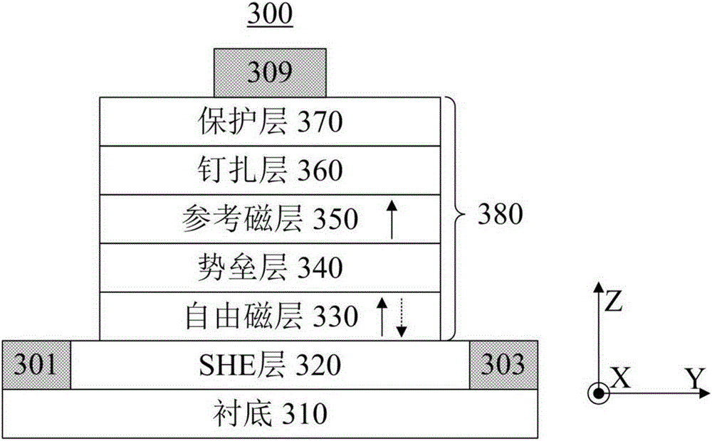
[0063] Using high vacuum magnetron sputtering equipment with SiO 2 The following thin films are deposited sequentially on the Si substrate of the surface layer: Pt(5nm) / Co(1.0nm) / Al 2 o 3 (3nm) / Co(0.8nm) / Pt(5nm). During the film preparation process, the background vacuum is better than 1.0×10 -5 Pa. The bottom Pt can be used as SHE layer, the top Pt can be used as protective layer, Co / Al 2 o 3 / Co constitutes the core region of the magnetic tunnel junction. Underlying Pt / Co / Al 2 o 3 The structure can ensure that the Co film as a free magnetic layer has good perpendicular anisotropy, while the top layer of Al 2 o 3 The / Co / Pt structure can ensure that the Co film used as a reference magnetic layer has good vertical anisotropy. The thickness of the Co layer used as the reference magnetic layer is 0.8 nm, which is less than 1.0 nm of the thickness of the Co layer used as the free magnetic layer, thereby ensuring that the reference magnetic layer has a larger coercive fo...
example 2
[0065] Using high vacuum magnetron sputtering equipment with SiO 2 The following thin films are deposited sequentially on the Si substrate of the surface layer: Ta(5nm) / Co 40 Fe 40 B 20 (1.2nm) / MgO(2.5nm) / Co 40 Fe 40 B 20 (1.0nm) / Ta(5nm) / Ru(5nm). During the film preparation process, the background vacuum is better than 1.0×10 -5 Pa. The bottom Ta is used as the SHE layer, and the top Ru layer is used as the protective layer. co 40 Fe 40 B 20 / MgO / Co 40 Fe 40 B 20 Constitutes the core region of the magnetic tunnel junction. Underlying Ta / Co 40 Fe 40 B 20 / MgO structure can guarantee Co as a free magnetic layer 40 Fe 40 B 20 The film has good vertical anisotropy, while the top MgO / Co 40 Fe 40 B 20 / Ta structure can guarantee the Co 40 Fe 40 B 20 The film has good vertical anisotropy. After the film was prepared, the sample was annealed in a vacuum annealing furnace at 300 °C and a magnetic field of 0.8 T for 1 hour, wherein the direction of the magneti...
example 3
[0081] Using high vacuum magnetron sputtering equipment with SiO 2 Prepare the following structure on the Si substrate of the surface layer: Ta(5nm) / Co 40 Fe 40 B 20 (1.2nm) / MgO(3nm) / Co 40 Fe 40 B 20 (0.8nm) / Ta(5nm) / Ru(5nm). During the preparation process, the background vacuum is better than 1.0×10 -5 Pa. Ru in the top layer can be used as a protective layer. co 40 Fe 40 B 20 / MgO / Co 40 Fe 40 B 20 Constitutes the core part of the magnetic tunnel junction. Underlying Ta / Co 40 Fe 40 B 20 / MgO structure can guarantee Co as a free magnetic layer 40 Fe 40 B 20 With perpendicular anisotropy, top MgO / Co 40 Fe 40 B 20 / Ta structure can guarantee the Co 40 Fe 40 B 20 Layers have perpendicular anisotropy. After the film was prepared, the sample was annealed in a vacuum annealing furnace at 325° C. and a magnetic field of 0.8 T for 1 hour. It should be noted that the direction of the magnetic field deviates from the Z-axis direction to, for example, the Y-axi...
PUM
 Abstract
Description
Claims
Application Information
 - R&D
- Intellectual Property
- Life Sciences
- Materials
- Tech Scout
- Unparalleled Data Quality
- Higher Quality Content
- 60% Fewer Hallucinations
Browse by: Latest US Patents, China's latest patents, Technical Efficacy Thesaurus, Application Domain, Technology Topic, Popular Technical Reports.
© 2025 PatSnap. All rights reserved.Legal|Privacy policy|Modern Slavery Act Transparency Statement|Sitemap|About US| Contact US: help@patsnap.com


