
Motor capable of realizing high-efficiency DC power

A power motor and power technology, applied in the field of DC power motors, can solve the problems of high-speed performance of magnet demagnetization, limited constant power range, poor safety and stability, etc., and achieve the effect of eliminating harmonics, light weight, and no iron loss

Inactive Publication Date: 2015-12-09
孟繁志
View PDF4 Cites 3 Cited by
  • Summary
  • Abstract
  • Description
  • Claims
  • Application Information

AI Technical Summary

Problems solved by technology

However, the cost of existing motors is high, and the existing motors used in automobiles still have problems such as limited constant power range, poor safety and stability, magnet demagnetization and low high-speed performance.

Method used

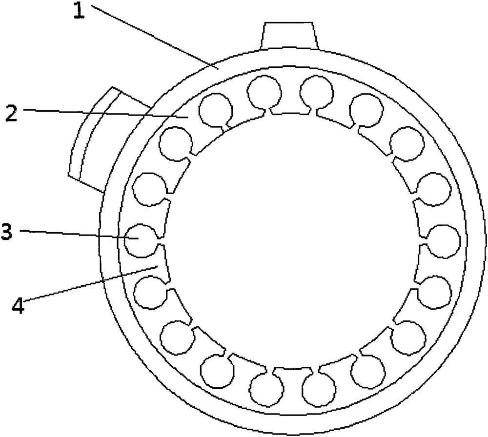
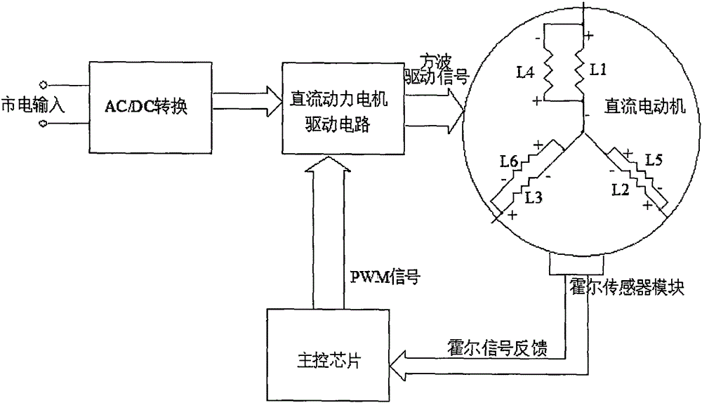

Image

  • Motor capable of realizing high-efficiency DC power
  • Motor capable of realizing high-efficiency DC power
  • Motor capable of realizing high-efficiency DC power

Examples


Embodiment 1

[0019] A motor capable of realizing high-efficiency DC power according to the present invention includes a rotor, a DC power motor drive circuit and a stator.

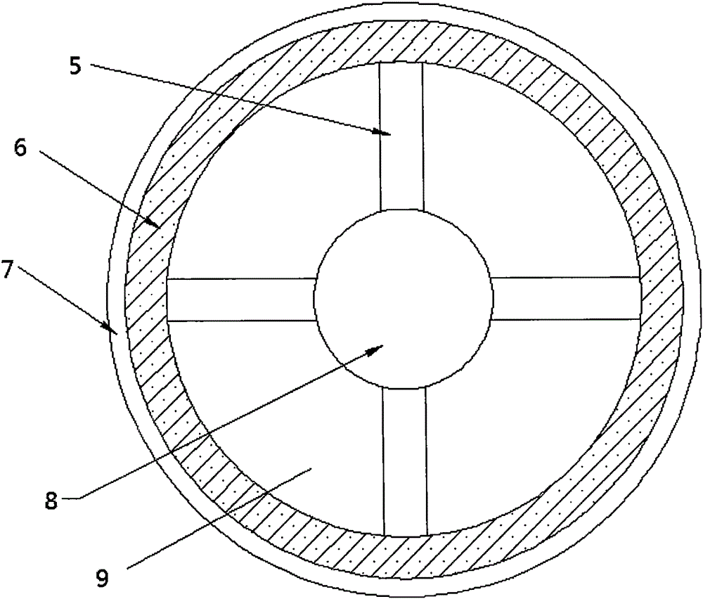
[0020] Such as figure 1 As shown: the rotor includes a rotor shaft 8, a rotor magnet bracket 5, a rotor magnet 6 and a reinforcement lining 7 that are sheathed in sequence from the inside to the outside, and the rotor magnet 6 is an integral structure composed of a tubular magnet. The material of the rotor magnet is bonded neodymium iron stilt, and the rotor magnet 6 is fixedly sleeved on the outer ring of the rotor magnet support 5. In terms of processing technology, the bonded magnetic material is easy to process and shape, compared with the rotor of the traditional DC power motor , the overall ring structure or multi-layer ring structure adopted by the present invention can magnetize the bonded NdFeS magnet into a standard sine wave magnetic pole, which reduces the torque ripple of the motor and makes the DC power m...

Embodiment 2

[0028] The difference between embodiment 2 and embodiment 1 lies in that the rotor magnet is a multi-layer structure composed of multi-layer tubular magnets arranged inside and outside in sequence. Of course, the material of the tubular magnet 15 is also bonded neodymium iron stilbium.

Embodiment 3

[0030] The difference between embodiment 3 and embodiment 1 is that the rotor magnet is an integrally cast integral structure rotor, which hardly generates heat when the motor is working, and can maintain the high-power working state of the motor without a cooling device.


PUM


Abstract

The invention provides a motor capable of realizing high-efficiency DC power, and belongs to the field of DC power motors. An adhesive Nd-Fe-B magnet is enabled to be magnetized into a standard sine wave magnetic pole by adopting an overall annular structure of a multilayer annular structure so that motor torque ripple is reduced, the DC power motor is enabled to generate stable high torque (high moment) under the condition of weak magnetism and low current. Besides, the structure of a rotor is enabled to be changed into a hollow structure so that the technical problem that the rotor structure cannot be changed into the hollow structure by the DC power motor can be solved, an effect of no generation of heat in operation of the motor can be achieved, and the motor can work under a high-power state without a cooling device.

Description

technical field [0001] The invention belongs to the field of DC power motors. Background technique [0002] With the needs of the rapid development of various motors and the invention of current magnetizers, people have conducted in-depth research on the mechanism, composition and manufacturing technology of permanent magnet materials, and have successively discovered carbon steel and tungsten steel (the maximum magnetic energy product is about 2.7kJ / m3 ), cobalt steel (maximum energy product about 7.2kJ / m3) and other permanent magnet materials. In particular, the AlNiCo permanent magnets (maximum energy product up to 85kJ / m3) that appeared in the 1930s and the ferrite permanent magnets (maximum energy product up to 40kJ / m3) that appeared in the 1950s have greatly improved their magnetic properties. Great improvement, various micro and small motors have used permanent magnet excitation. The power of permanent magnet DC motors is as small as a few milliwatts and as large as...

Claims


Application Information

Patent Timeline
IPC IPC(8): H02K1/27H02K1/16H02K3/16
Inventor 孟繁志白晓东
Owner 孟繁志
Learn More