Eureka AIR delivers breakthrough ideas for toughest innovation challenges, trusted by R&D personnel around the world.

Permanent magnet synchronous motor without stator iron core

A permanent magnet synchronous and motor technology, applied in synchronous machines, magnetic circuit rotating parts, electrical components, etc., can solve the problems of bad sine wave of air-gap flux density, increased motor torque pulsation, and inflexible control methods. Achieve the effect of light weight, elimination of torque ripple and low loss

Inactive Publication Date: 2010-07-21
BEIHANG UNIV
View PDF2 Cites 26 Cited by
  • Summary
  • Abstract
  • Description
  • Claims
  • Application Information

AI Technical Summary

Problems solved by technology

However, when only the Halbach magnet structure is used, there will still inevitably be harmonic components in the air-gap flux density waveform, which makes the sine of the air-gap flux density waveform not good, and the harmonic components increase the torque ripple of the motor. Generally, for permanent magnets with Halbach magnetization method, the magnetic steel is a surface-mounted structure, and it is assembled into a ring structure, which is a hidden pole structure in the electrical structure. Control Strategy
Due to the above defects, the existing Halbach magnetized statorless core permanent magnet synchronous motor has the disadvantages of poor stability when output torque and inflexible control mode

Method used


Image

  • Permanent magnet synchronous motor without stator iron core
  • Permanent magnet synchronous motor without stator iron core
  • Permanent magnet synchronous motor without stator iron core

Examples


Embodiment Construction

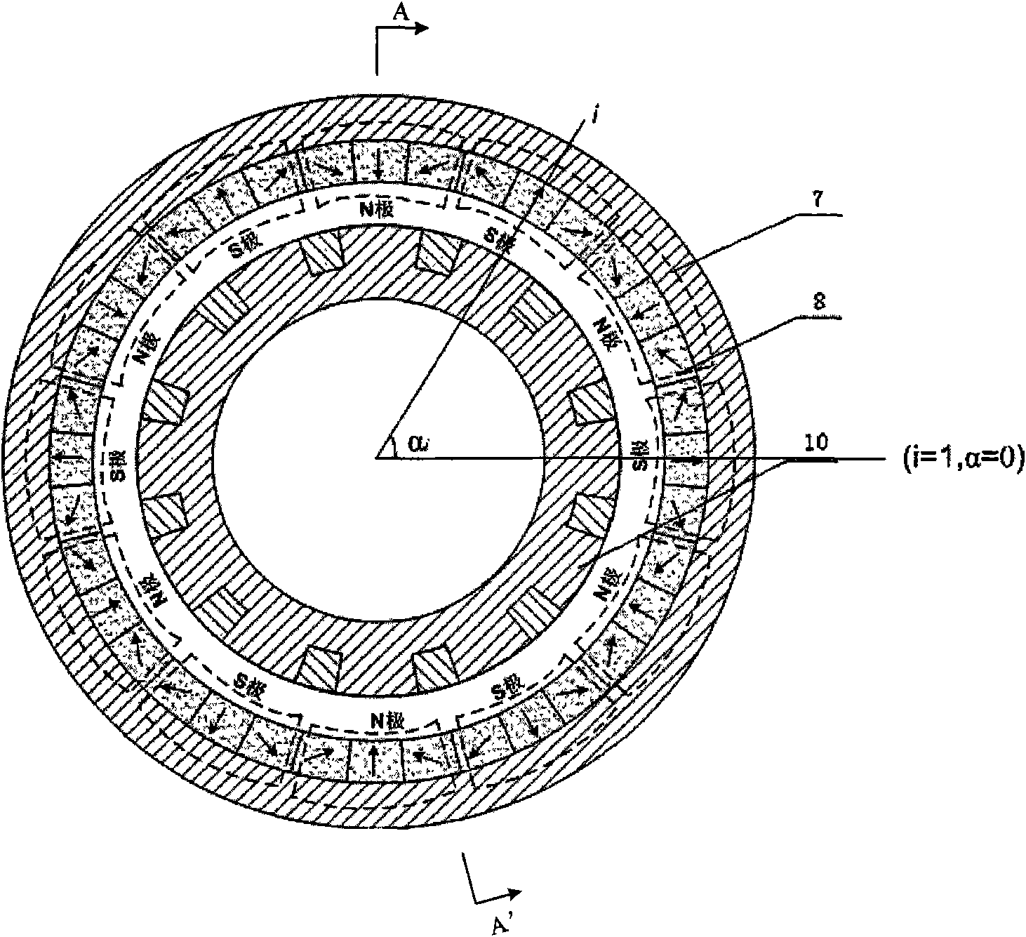
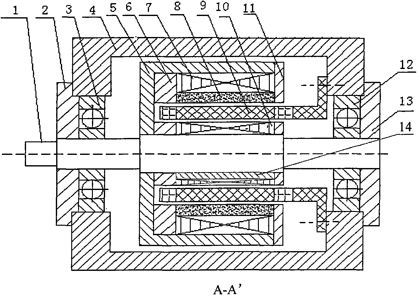
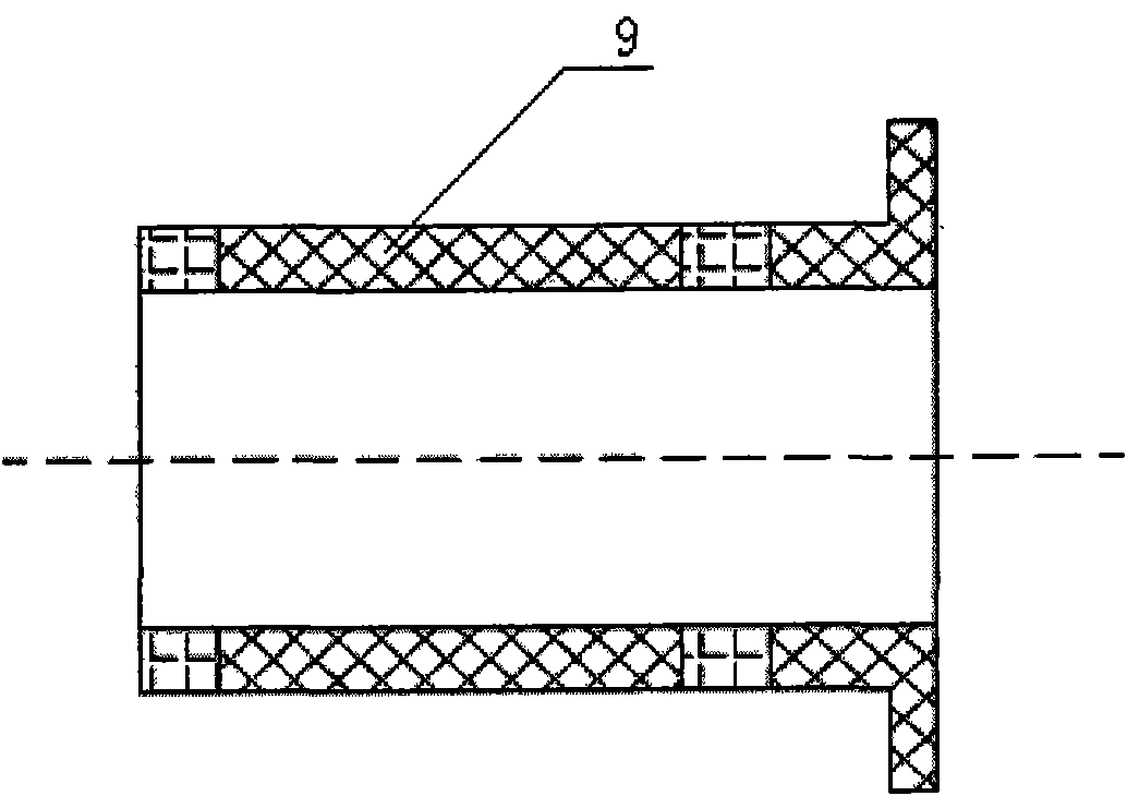
[0019] Such as figure 2 As shown, the stator coreless permanent magnet synchronous motor of the present invention consists of a rotor shaft 1, a left end cover 2, a left bearing 3, a housing 4, a sleeve 5, a left retaining ring 6, an outer rotor core 7, a motor magnetic steel 8, a hollow Cup stator 9 (including skeleton and fractional slot concentrated winding), inner rotor core 10, right retaining ring 11, right bearing 12, right end cover 13, magnetic isolation block 14, hollow cup stator 9 is fixed on the shell 4 through its base , the radial outer side is the motor magnet 8, the radial inner side is the inner rotor core 10, the motor magnet 8 is connected to the outer rotor core 7, the inner rotor core 10, the outer rotor core 7 and the motor magnet 8 are connected through the sleeve 5 On the rotor shaft 1, the left retaining ring 6 is located on the left end face of the outer rotor core 7 and the motor magnetic steel 8, and is connected with the sleeve 5, and its thickne...


PUM


Abstract

The invention relates to a permanent magnet synchronous motor without a stator iron core, which mainly comprises a rotor shaft, an inner rotor iron core, a magnetic isolation block, a hollow cup stator (including a skeleton and a fractional slot concentrated winding), a Halbach permanent magnet and an outer rotor iron core, wherein the magnetic isolation block is embedded in the inner rotor iron core and forms an inner rotor core component part with the inner rotor iron core, the inner rotor iron core, the outer rotor iron core and the permanent magnet are all connected with the rotor shaft, the Halbach permanent magnet is stuck to the outer rotor iron core, and the hollow cup stator is fixed on a motor shell. The permanent magnetic circuit is formed into a closed loop circuit via the inner rotor iron core, the magnetic air gap, the Halbach permanent magnet and the outer rotor iron core. The invention utilizes the magnetic isolation block to achieve a salient pole structure of the motor so as to realize control by the difference of A-axis and D-axis inductance, the concentrated winding is utilized to weaken harmonic content in winding induced electromotive force and greatly increase the sinusoidal property of the winding induced electromotive force and winding current, so the torque impulse is reduced, and the stationarity of the output torque is improved.

Description

technical field [0001] The invention relates to a permanent magnet synchronous motor, especially a salient pole type stator coreless permanent magnet synchronous motor with good sinusoidal induced electromotive force, belonging to the field of motors, suitable for high speed and low power consumption occasions, especially for Induction electromotive force sine wave waveform requirements are higher occasions. Background technique [0002] Due to the existence of the stator core in the traditional permanent magnet synchronous motor, hysteresis and eddy current loss will be generated in the stator core when the motor is running. These losses are proportional to the 1.3 power of the rotor rotation frequency. When the rotor rotates at a high speed, it will A huge loss is generated in the stator core, which greatly increases the power consumption of the motor; at the same time, due to the existence of the stator cogging, the cogging torque and tooth harmonics will be generated whe...

Claims


Application Information

Patent Timeline
Patent Type & Authority Applications(China)
IPC IPC(8): H02K21/00H02K16/02H02K1/16H02K1/27
Inventor 房建成王春娥孙津济汤继强杨云帆
Owner BEIHANG UNIV
Why Eureka
Eureka Blog
Learn More