A production and processing equipment for cross wedge rolling

A processing equipment and technology of cross wedge rolling, applied in the field of round steel cross wedge rolling production and processing equipment, can solve the problems of shortened service life of rolling mills, waste of steel, and many processes, so as to improve rolling efficiency, reduce production costs, and reduce processes Effect

Active Publication Date: 2018-09-25
山东泰金精锻股份有限公司
View PDF1 Cites 0 Cited by
  • Summary
  • Abstract
  • Description
  • Claims
  • Application Information

AI Technical Summary

Problems solved by technology

[0003] At present, the rolling method commonly used in the production of round steel cross wedge rolling is to first cut the whole round steel into short bars of corresponding length according to the length of the rolled piece, and then heat and roll in turn. The weak point that the method exists is: the one, because earlier whole round steel is cut into short bar stock and just can be heated and rolled, so operation is many, efficiency is low; The two ends of the parts must be cut off on the rolling mill, so a lot of scrap ends are generated, resulting in waste of steel and increasing production costs
[0004] In order to realize the continuous rolling of the whole round steel during the cross wedge rolling production, our company has also applied for the combination device of cross wedge rolling with continuous heat and continuous rolling with the patent number ZL200620087374.2, but this cross wedge rolling with continuous heat The continuous rolling combination device has the following technical defects in the use process: ①The entire round steel pinch mechanism is operated by the cooperation of the push cylinder and the clamping wheel. When feeding, the length of the push rod of the push cylinder is constant. When the feeding of the round steel is about to end, the feeding effect is not ideal; in order to ensure the precision of the rolling during heating and rolling, and to reduce the output rate of the scrap head of the round steel to the greatest extent, it is necessary to adjust the length of each feeding Accurately limited, but the length of each feed of the push cylinder is not easy to control, resulting in an excessively high output rate of scrap heads, resulting in waste of steel; , due to the inertia effect, it will have a great impact on the rolling mill body, which will shorten the service life of the rolling mill, and may cause production accidents after a long time; on the other hand, the position where the round bar stops moving often deviates from the working position area of ​​the rolling mill , which increases the output rate of waste heads; ③When the round steel is rolled by the cross wedge rolling mill, the round steel will be in a rotating state. Due to the lack of corresponding sensing devices, the information cannot be transmitted to the frequency conversion motor in time, and the driving wheel and the drive wheel cannot be realized. The round steel rotates synchronously at the same speed, which may easily cause local distortion of the round steel and affect the product quality; ④When the round steel is transferred from the round steel storage rack to the supporting wheel, it will have a large vertical impact on the bearing seat of the supporting wheel Force, due to the lack of corresponding buffer devices, with the prolongation of the use time, it will cause the phenomenon of open welding of the bearing seat of the supporting wheel, which may cause production accidents in severe cases

Method used


Image

  • A production and processing equipment for cross wedge rolling
  • A production and processing equipment for cross wedge rolling
  • A production and processing equipment for cross wedge rolling

Examples


Embodiment Construction

[0028]The following will clearly and completely describe the technical solutions in the embodiments of the present invention with reference to the accompanying drawings in the embodiments of the present invention. Obviously, the described embodiments are only some, not all, embodiments of the present invention. Based on the embodiments of the present invention, all other embodiments obtained by persons of ordinary skill in the art without creative efforts fall within the protection scope of the present invention.

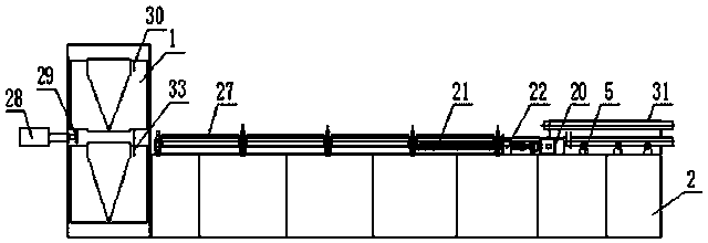
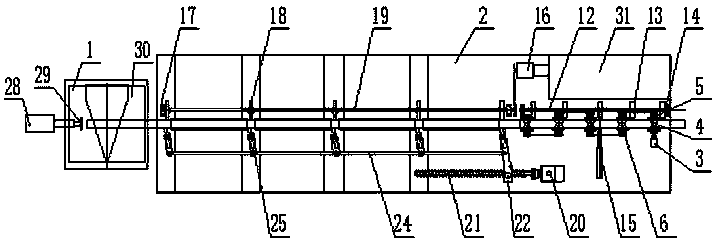
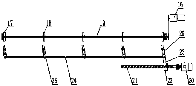
[0029] Such as figure 1 , 2 As shown, the present invention includes a frame 2, a cross wedge rolling mill 1, a round steel storage rack 31, a round steel turning mechanism, a round steel follow-up mechanism, a buffer receiving mechanism, a round steel clamping and conveying mechanism, and an intermediate frequency segmental induction heating furnace 27. The buffer positioning mechanism, the second photoelectric sensor 30 and the third photoelectric sensor 33. The...


PUM

PropertyMeasurementUnit
lengthaaaaaaaaaa

Abstract

The invention relates to cross wedge rolling production and processing equipment. The equipment comprises a round steel following and conveying mechanism, a buffering and bearing mechanism, a round steel clamping and conveying mechanism, a buffering and positioning mechanism, a second photoelectric sensor and a third photoelectric sensor. The buffering and bearing mechanism comprises a bearing plate, second cylinders and springs. The round steel clamping and conveying mechanism comprises a round steel rotating and driving device and a round steel horizontal-moving and driving device. The round steel rotating and driving device comprises a variable frequency motor, supports, driving wheels and a rotating shaft. The round steel horizontal-moving and driving device comprises a stepping motor, a lead screw, a moving block, a push rod, a drive rod and eccentric balance wheels. The buffering and positioning mechanism comprises a third air cylinder, an air pump and a first photoelectric sensor. The second photoelectric sensor and the third photoelectric sensor are arranged inside a cross wedge rolling machine. The second photoelectric sensor is in line connection with an electromagnetic valve of the variable frequency motor. The third photoelectric sensor is in line connection with an electromagnetic valve of the stepping motor. Compared with the prior art, the cross wedge rolling production and processing equipment has the advantage of being high in rolling efficiency.

Description

technical field [0001] The invention relates to a production and processing equipment, in particular to a round steel cross wedge rolling production and processing equipment integrating round steel conveying, continuous heating and rolling. Background technique [0002] Cross wedge rolling refers to the continuous local deformation of the cylindrical billet between the dies of two rollers or between two flat dies, and the shape of the rolled part is consistent with the shape of the groove at the bottom of the die. Cross wedge rolling can be roughly divided into two categories: roll cross wedge rolling and plate cross wedge rolling. Among them, the forming principle of roller cross wedge rolling: two rollers rotate in the same direction, driving the circular billet to rotate in the opposite direction, so that the shape of the rolled part is consistent with the shape of the groove at the bottom of the mold. [0003] At present, the rolling method commonly used in the producti...

Claims


Application Information

Patent Timeline
Patent Type & Authority Patents(China)
IPC IPC(8): B21B1/00B21B1/08B21B39/02B21B39/20B21B39/34
CPCY02P70/10
Inventor 李传斌于涛吴修成陶润祥
Owner 山东泰金精锻股份有限公司
Why Eureka
Try Eureka