A powder feeding device and method of using the same
A powder feeding device and powder feeding nozzle technology are applied in the coating process and coating of metal materials, which can solve the problems affecting the surface flatness of the cladding layer, reduce the utilization rate, increase the production cost, etc., and achieve convenient disassembly and maintenance. , the effect of reducing cost input and improving work efficiency
- Summary
- Abstract
- Description
- Claims
- Application Information
AI Technical Summary
Problems solved by technology
Method used
Image
Examples
Embodiment 1
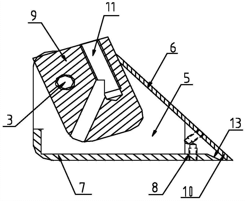
[0032] Such as figure 1 As shown, a powder feeding device includes a buffer part 1 and a buffer part 2 movably connected by a fastener 3, which is convenient for adjusting the angle between the buffer part 1 and the buffer part 2, and then flexibly adjusts powder feeding angle, and each component is easy to disassemble and maintain, which improves work efficiency, especially the powder feeding nozzle 5 is a consumable item in actual production. When the powder feeding nozzle 5 is damaged, all parts only need to be disassembled, Only the powder feeding nozzle 5 needs to be replaced to reduce the cost input.
[0033] Such as Figure 1-3 As shown, the buffer component 1 includes a powder feeding pipe 4 and a rotating head 9, the rotating head 9 is arranged at the end of the powder feeding pipe 4, and the alloy powder reaches the rotating head 9 from the powder feeding pipe 4, and the The inside of the rotating head 9 is provided with a curve 11, the angle of the curve 11 is set...
Embodiment 2
[0036] Such as image 3 As shown, the intersection of the upper regulating plate 6 and the lower regulating plate 7 is provided with a powder outlet 10, and the inclination direction of the curve 11 is opposite to the direction of the powder outlet 10, and the alloy powder reaches the powder feeding nozzle 5 Inside, it is conveyed to the powder outlet 10, the conveying direction is changed, the second buffering effect is completed, and it is discharged through the powder outlet 10.
[0037] The powder outlet 10 is set as a slope structure 13, and the angle between the slope structure 13 and the horizontal plane is set to 25-30°. Under the joint action of the slope structure 13 and the upper regulating plate 6, the alloy powder is formed Again buffering effect, high uniformity of powder feeding, high utilization rate of alloy powder, effectively improving the surface smoothness of cladding layer.
[0038] Such as figure 1 , Figure 4 As shown, the insides of the upper adjust...
Embodiment 3
[0041] Such as Figure 1-4 As shown, using the powder feeding device, the specific work includes the following steps:
[0042] (1) By adjusting the fastener one 3, adjust the angle between the buffer part one 1 and the buffer part two 2, so that the angle between the powder feeding nozzle 5 and the vertical direction is 40-70° to achieve uniform feeding The purpose of powder;
[0043] (2) The alloy powder slides down from the powder feeding pipe 4, reaches the rotating head 9, and realizes the first buffering effect in the curve 11, changes the conveying direction, and reduces the conveying speed;
[0044] (3) The alloy powder arrives in the powder delivery nozzle 5 from the rotating head 9, and is transported to the powder outlet 10 to realize the second buffering effect, change the transport direction, and reduce the transport speed;
[0045] (4) Slide the upper adjusting plate 6 and the lower adjusting plate 7 along the powder feeding nozzle 5 to change the size and powde...
PUM
 Abstract
Description
Claims
Application Information
 - R&D
- Intellectual Property
- Life Sciences
- Materials
- Tech Scout
- Unparalleled Data Quality
- Higher Quality Content
- 60% Fewer Hallucinations
Browse by: Latest US Patents, China's latest patents, Technical Efficacy Thesaurus, Application Domain, Technology Topic, Popular Technical Reports.
© 2025 PatSnap. All rights reserved.Legal|Privacy policy|Modern Slavery Act Transparency Statement|Sitemap|About US| Contact US: help@patsnap.com


