A New Type of Solid State Relay
A solid-state relay, a new type of technology, applied in the direction of electrical components, electronic switches, pulse technology, etc., can solve the problems of high price and restrictions on the promotion and use of solid-state AC relays, and achieve high versatility, wide application range, and low on-state voltage. Effect
- Summary
- Abstract
- Description
- Claims
- Application Information
AI Technical Summary
Problems solved by technology
Method used
Image
Examples
Embodiment 1
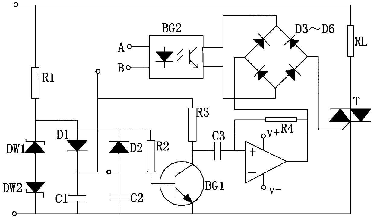
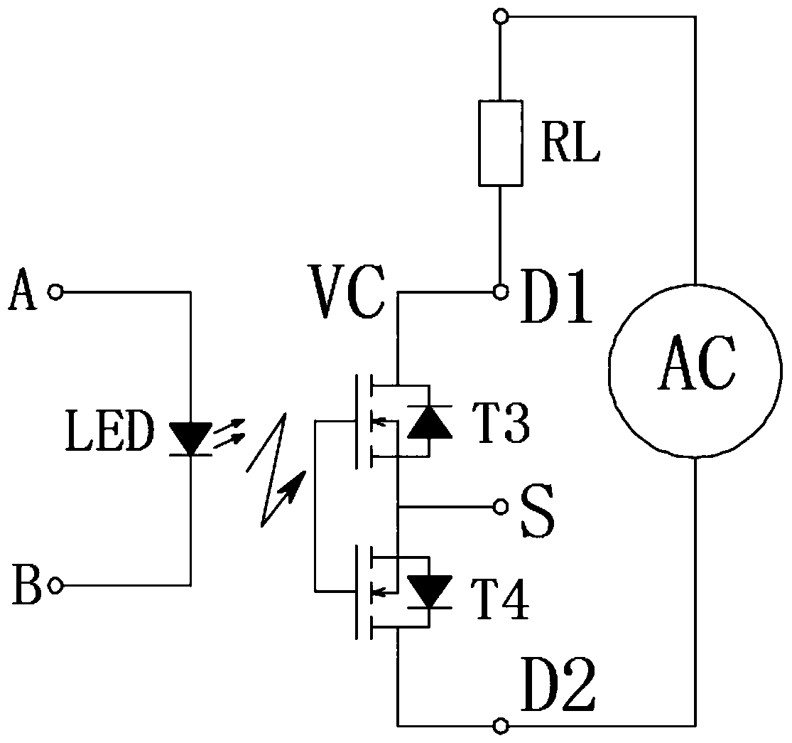
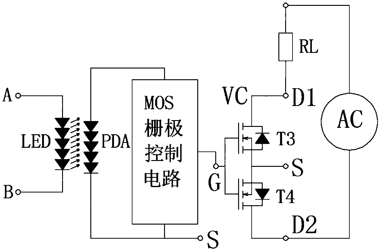
[0024] combine Figure 4, a new type of solid state relay in this embodiment, including a control input terminal, an isolation circuit, a trigger drive circuit, a logic flip circuit, an output circuit, and a floating DC stabilized power supply. The floating DC stabilized power supply includes a first resistor R1, a rectifier Diode Q3, energy storage capacitor C, bidirectional voltage regulator diode D1, one end of the first resistor R1 is connected to the common terminal COM, the other end of the first resistor R1 is connected to the anode of the rectifier diode Q3, and the cathode of the rectifier diode Q3 is respectively connected to the energy storage capacitor The anode VC of C and the first end of the bidirectional voltage regulator diode D1, the negative pole S of the energy storage capacitor C is connected to the second end of the bidirectional voltage regulator diode D1; the control input end includes the second resistor R2 and the first light emitting diode LED1, the ...
Embodiment 2
[0029] combine Figure 5 , the basic circuit connection of a new type of solid-state relay in this embodiment is the same as in Embodiment 1, the disadvantage is that the load circuit is a DC load, the load circuit includes a load RL and a direct current DC, and the positive pole of the direct current DC is connected to the common terminal COM and then connected to the load One end of the RL, the other end of the load RL is connected to the first output end d1, and the negative pole of the direct current DC is connected to the second output end d2.
Embodiment 3
[0031] combine Figure 6 , the basic circuit connection of a new type of solid-state relay in this embodiment is the same as in Embodiment 1, the disadvantage is that the load circuit is a DC load, the load circuit includes a load RL and a direct current DC, and the positive pole of the direct current DC is connected to the common terminal COM and then connected to the load One end of the RL, the other end of the load RL is connected to the first output end d1, and the negative pole of the direct current DC is connected to the third output end s.
PUM
 Abstract
Description
Claims
Application Information
 - R&D
- Intellectual Property
- Life Sciences
- Materials
- Tech Scout
- Unparalleled Data Quality
- Higher Quality Content
- 60% Fewer Hallucinations
Browse by: Latest US Patents, China's latest patents, Technical Efficacy Thesaurus, Application Domain, Technology Topic, Popular Technical Reports.
© 2025 PatSnap. All rights reserved.Legal|Privacy policy|Modern Slavery Act Transparency Statement|Sitemap|About US| Contact US: help@patsnap.com


