
Mobile medical equipment and power supply device used for same

A technology for power supply devices and medical equipment, which is applied to circuit devices, battery circuit devices, and instruments for radiological diagnosis, etc. It can solve problems such as short cycle life, battery safety, and slow charging speed, and achieve light weight and high safety. sexual effect

Active Publication Date: 2015-11-04
SHENZHEN MINDRAY BIO MEDICAL ELECTRONICS CO LTD
View PDF8 Cites 6 Cited by
  • Summary
  • Abstract
  • Description
  • Claims
  • Application Information

AI Technical Summary

Problems solved by technology

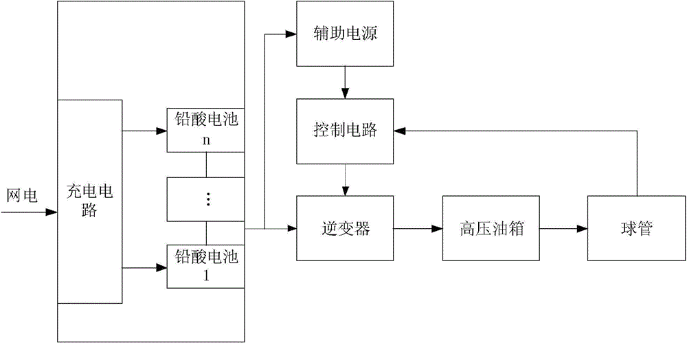
[0009] An object of the present invention is to provide a mobile medical device and a power supply device used therefor, so as to solve the problem of large volume and weight, slow charging speed, short cycle life and reliability problems of lead-acid batteries existing in existing mobile medical devices. low problem
[0010] Another object of the present invention is to provide a mobile medical device and the power supply device used therein to solve the safety problems that may occur in the existing mobile medical device due to the short circuit of the battery or the short circuit of the subsequent circuit

Method used


Image

  • Mobile medical equipment and power supply device used for same
  • Mobile medical equipment and power supply device used for same
  • Mobile medical equipment and power supply device used for same

Examples


Embodiment 1

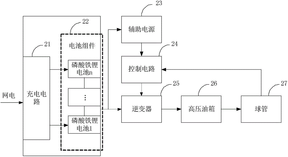
[0024] In view of the problems existing in the use of lead-acid batteries in mobile X-ray machines on the market, the present invention adopts lithium-ion batteries to replace the application of lead-acid batteries in mobile X-ray machines. Lithium-ion batteries can also be referred to as lithium batteries for short, and their characteristics include the following (1)~(4).

[0025] (1) Light weight and volume: Under the same specification and capacity, the volume of lithium-ion batteries is about 2 / 3 of that of lead-acid batteries, and the weight is 1 / 3 of that of lead-acid batteries;

[0026] (2) Ultra-long life: the cycle life of lead-acid batteries is 500 times, and the service life is short, while the cycle life of lithium-ion batteries can reach 800-1000 times, the service life is long, and the performance-price ratio is 4 times that of lead-acid batteries. more than double;

[0027] (3) Lithium-ion batteries can realize high-current fast charge and discharge, while lead...

Embodiment 2

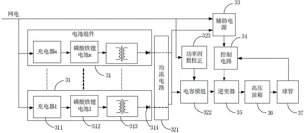
[0042] Such as image 3 As shown, in the mobile X-ray machine of this embodiment, the power supply control mechanism of the whole machine is as follows image 3 As shown, it includes a power supply device, an auxiliary power supply 33, a control circuit 34, an inverter 35, a high-pressure oil tank 36 and a bulb 37, wherein the power supply device includes a current equalizing circuit 321, a capacitor module 322 and n groups connected in parallel (n is positive Integer) power supply components 31, each set of power supply components 31 includes a charger 311, a battery component 312 and a booster circuit 313 connected in series, wherein the battery component 312 is composed of at least one lithium-ion battery connected in series. exist image 3 In the illustrated embodiment, the lithium ion battery is a lithium iron phosphate lithium ion battery, and other types of lithium ion batteries may also be used in other embodiments.

[0043] The boost circuit 313 is used for boosting...

Embodiment 3

[0055] This embodiment is based on Embodiment 2, adding switching devices to further improve the safety and reliability of battery use, still as image 3 As shown, each set of power components 31 further includes a switch device 314 connected in series between the boost circuit 313 and the current equalizing circuit 321 of the corresponding power component. In a specific implementation, the switching device 314 can be realized by using, for example, a diode to ensure unidirectional conduction from the DC power supply module to the capacitor module and the auxiliary power supply, so as to prevent the current flow to other circuits when a certain power supply component 31 is abnormal. pour back.


PUM


Abstract

A medical diagnostic high-frequency X-ray machine and a power supply apparatus. The power supply apparatus can convert a mains alternating current into a direct current by adding alternating-current direct-current converters (121, 421, 521), boost circuits (131, 313, 432) and capacitor modules (14, 322, 44), and then provide, through boost and stored energy of the boost circuits (131, 313, 432) and the capacitor modules, a high voltage and sufficient energy for inverters (15, 35, 45), so that the inverters (15, 35, 45) obtains a high-voltage direct-current from the capacitor modules (14, 322, 44) and outputs a high-frequency alternating-current after inversion, and in this manner, the medical diagnostic high-frequency X-ray machine can use mains power supply. Another power supply apparatus uses lithium iron phosphate batteries as battery components (312, 422, 522) to supply power to the medical diagnostic high-frequency X-ray machine, thereby making the power supply apparatus of the medical diagnostic high-frequency X-ray machine lighter, small-sized, high temperature-resistant, quick in charge and discharge and safer.

Description

technical field [0001] The invention relates to the technical field of mobile medical devices, in particular to a mobile medical device and a power supply device used therein. Background technique [0002] Medical device manufacturers are no exception to the growing emphasis on product mobility in many industries, a trend that is driving the healthcare industry by improving the performance of first aid equipment, monitoring equipment, and stationary medical equipment. In addition, the mobility of patients is becoming more and more important, and may be transferred from one department to another, or from an ambulance to an emergency room, etc. Therefore, the application of mobile medical equipment is getting wider and wider. Take the mobile digital medical diagnostic high-frequency X-ray machine (DR, Digital Radiography) as an example. It can be used in orthopedics, wards, emergency rooms, operating rooms, ICU and other occasions in a mobile way to digitize various parts of ...

Claims


Application Information

Patent Timeline
Patent Type & Authority Applications(China)
IPC IPC(8): H02J7/00A61B6/00
CPCA61B6/00H02J7/02H05G1/10H05G1/12A61B6/4405A61B6/56Y02E60/10
Inventor 张皖刘学东
Owner SHENZHEN MINDRAY BIO MEDICAL ELECTRONICS CO LTD
Learn More