An Indoor Positioning System Based on Multiple Existing Communication Networks

A communication network and indoor positioning technology, which is applied in the field of indoor positioning systems, can solve the problems of high cost, short distance, and low cost, and achieve the effects of accurate positioning data, reducing errors, and improving accuracy

Active Publication Date: 2018-04-27
TONGJI UNIV
View PDF5 Cites 0 Cited by
  • Summary
  • Abstract
  • Description
  • Claims
  • Application Information

AI Technical Summary

Problems solved by technology

[0004] The RFID system is generally based on the signal arrival time difference for positioning, and the positioning accuracy is 2-3 meters. Its advantages are non-line-of-sight, small size, and low cost. However, various devices including clocks, amplifiers, and radio frequency circuits are complex. higher
Ultrasonic positioning accuracy is high, but it requires special hardware and is greatly affected by non-line-of-sight and multipath propagation
Ultra-wideband technology has high positioning accuracy, strong penetrating power, and good anti-multipath effect, but the cost is high and theoretical research is insufficient
Using infrared positioning can obtain the highest positioning accuracy of millimeter level, easy to install, but very easy to be interfered by room lights
The average positioning error of Zigbee technology is 3-5 meters, the cost is low, but the distance is short, and a large number of sensors are required to form a network, which is difficult to promote and apply on a large scale
WLAN positioning can be based on signal strength and angle of arrival. The average error is 1-3 meters. The disadvantage is that the resolution of signal strength is limited and it is easily affected by multipath.

Method used


Image

  • An Indoor Positioning System Based on Multiple Existing Communication Networks
  • An Indoor Positioning System Based on Multiple Existing Communication Networks
  • An Indoor Positioning System Based on Multiple Existing Communication Networks

Examples


Embodiment 1

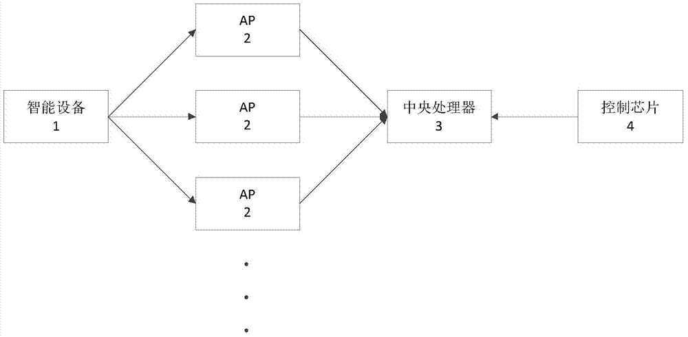
[0035] Such as figure 1As shown, an indoor positioning system based on multiple existing communication networks includes multiple AP2s, smart devices 1 to be positioned, a control chip 4 and a central processing unit 3, and multiple AP2s are wirelessly connected to the smart devices 1 through their respective communication networks, The central processing unit 3 is connected to the AP2 through an optical fiber, and the control chip 4 is connected to the central processing unit 3 . Wherein, the communication network includes GSM, WCDMA, LTE, CDMA and WIFI network. AP2 This is the network access point in the room itself, such as the access point of WIFI. The smart device 1 is a user's hand-held mobile device: such as a mobile phone, which is the device to be positioned by the system. The control core switches between different commercial networks, and can also choose to use different AP2s indoors. The central processing unit 3 can make different commercial communication netwo...

Embodiment 2

[0049] The difference between this embodiment and Embodiment 1 is that there is only one communication network between AP2 and smart device 1. At this time, although a single AP2 has only one communication network, there are actually many such AP2s under this indoor communication network. Processor 3 obtains the AOA data corresponding to AP2 under the communication network according to the signal received by AP2 under the same communication network and adopts the AOA estimation algorithm, and then combines the position information of AP2 with a geometric method to obtain the set of position information of the smart device 1 under the communication network , and compare the sets of location information of the smart device 1 under different communication networks to obtain the optimal location information of the smart device 1 .

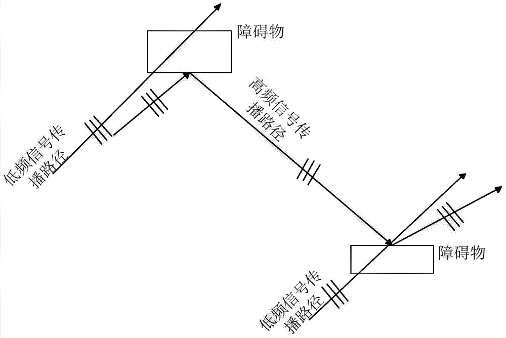
[0050] Among them, the communication network is divided into high-frequency network and low-frequency network, because the diffraction ability of high-...

Embodiment 3

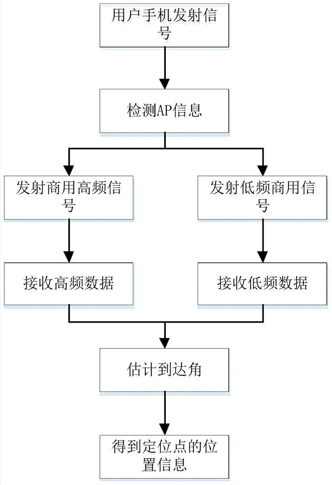
[0054]The difference between this embodiment and Embodiment 1 is that four AP2s are set indoors. The user's mobile phone can be used as a transmitting signal source, and the signal source transmits signals to four AP2s. The system starts to run under the action of the control chip 4 (the control code is written in the chip): for example, the system first automatically selects the WIFI frequency band with a frequency of 2.4GHz, and returns the signal received by AP2 to the central processing unit 3; then the system selects The GSM signal with a frequency of 450MHz is received in the same way. Then the central processing unit 3 starts to run, and the system uses a high-precision AOA estimation algorithm to start computing the data, and the system obtains four AOA estimation results through four signals received by AP2 under the WIFI signal; use the same method to obtain The results of four AOA estimations under GSM signal are presented. Comparing the AOA of different AP2s unde...


PUM


Abstract

The invention relates to an indoor positioning system based on multiple existing communication networks. The indoor positioning system comprises a plurality of APs and an intelligent device to be positioned. The indoor positioning system further comprises a control chip and a central processor; the plurality of APs are wirelessly connected with the intelligent device through respective communication networks; the central processor is connected with the APs; the control chip is connected with the central processor; the plurality of APs communicate with the intelligent device through respective communication networks and receive signals; the central processor acquires the position information of the intelligent device according to the signals received by the plurality of APs; and the control chip selects communication networks of the APs and the intelligent device and APs which communicate with the central processor. Compared with the prior art, and according to the indoor positioning system of the invention, based on the difference of diffraction abilities and the difference of positioning precisions of signals of different frequencies, indoor combined positioning is performed. The indoor positioning system has the advantages of high measurement precision, simple structure, low cost and the like.

Description

technical field [0001] The invention relates to the field of wireless communication, in particular to an indoor positioning system based on multiple existing communication networks. Background technique [0002] With the progress of society, the continuous development of information technology, and the drive of business, people's requirements for accurate indoor positioning services are becoming more and more urgent. For example, when people are in a large shopping mall, when a fire breaks out, traditional GPS positioning signals cannot penetrate high-rise buildings, so the positioning system fails, and firefighters cannot locate people who may be in a coma, thus delaying the best time for treatment. Therefore, there is an urgent need for an accurate indoor positioning technology, which can find people in distress by locating the user's smart handheld device. In recent years, indoor positioning technology has gradually become a research hotspot, constantly attracting the at...

Claims


Application Information

Patent Timeline
Patent Type & Authority Patents(China)
IPC IPC(8): H04W64/00H04W16/20
CPCH04W16/20H04W64/003H04W64/006
Inventor 周俊鹤王辉胡青松吉地辽日张健
Owner TONGJI UNIV
Why Eureka
Try Eureka