Manufacturing method of liquid-propellant rocket engine combustion chamber
A technology of liquid rockets and manufacturing methods, applied in the direction of rocket engine devices, machines/engines, mechanical equipment, etc., can solve the problems of low welding strength, high cost, complicated process, etc., and achieve high processing efficiency, good reliability, and simple operation Effect
- Summary
- Abstract
- Description
- Claims
- Application Information
AI Technical Summary
Problems solved by technology
Method used
Image
Examples
Embodiment 1
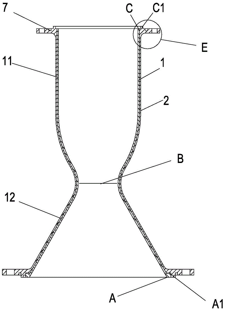
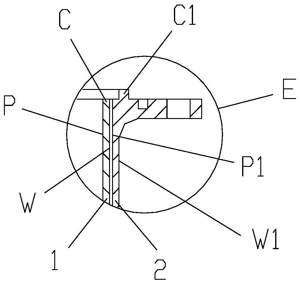
[0026] The structure of the combustor of a certain type of liquid rocket engine is as follows: figure 1 and figure 2 Shown in an hourglass shape, it is a copper alloy inner wall and a stainless steel outer wall. The largest diameter of the shape is connected to the injector port. The diameter d is 460mm, and the length H is 560mm. The manufacturing method of the combustion chamber includes the following steps:
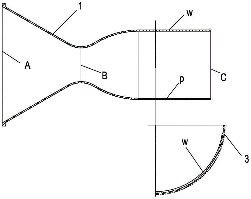
[0027] 1) For the inner wall 1, the structure is as image 3 As shown, the front sealing end surface A of the inner wall connected to one end of the injector and the rear sealing end surface C of the inner wall connected to the end of the tail nozzle, and the shape of the inner wall between the front sealing end surface A of the inner wall and the rear sealing end surface C of the inner wall The surface W is subjected to finishing treatment, and the liquid fuel self-circulation cooling channel 3 is arranged on the outer surface W of the inner wall;
[0028] 2) On th...
Embodiment 2
[0039] For a certain type of liquid rocket engine combustion chamber, its structure is as follows figure 1 and figure 2 Shown in an hourglass shape, it is a copper alloy inner wall and a stainless steel outer wall. The largest diameter of the shape is connected to the injector port. The diameter d is 660mm, and the length H is 560mm. The manufacturing method of the combustion chamber includes the following steps:
[0040] 1) For the inner wall 1, the structure is as image 3As shown, the front sealing end surface A of the inner wall connected to one end of the injector and the rear sealing end surface C of the inner wall connected to the end of the tail nozzle, and the shape of the inner wall between the front sealing end surface A of the inner wall and the rear sealing end surface C of the inner wall The surface W is subjected to finishing treatment, and the liquid fuel self-circulation cooling channel 3 is arranged on the outer surface W of the inner wall;
[0041] 2) On ...
PUM
| Property | Measurement | Unit |
|---|---|---|
| Thickness | aaaaa | aaaaa |
Abstract
Description
Claims
Application Information
 - R&D Engineer
- R&D Manager
- IP Professional
- Industry Leading Data Capabilities
- Powerful AI technology
- Patent DNA Extraction
Browse by: Latest US Patents, China's latest patents, Technical Efficacy Thesaurus, Application Domain, Technology Topic, Popular Technical Reports.
© 2024 PatSnap. All rights reserved.Legal|Privacy policy|Modern Slavery Act Transparency Statement|Sitemap|About US| Contact US: help@patsnap.com


