
Integral full-ceramic super dense-tooth three-edge milling cutter and manufacturing method thereof

A manufacturing method and technology of side edge milling, which is applied in the direction of milling cutters, manufacturing tools, milling machine equipment, etc., can solve the problems of large amount of material removal and inability to apply side edge milling cutters, etc., and achieve good chemical stability, which is conducive to chip breaking and Effect of recycling and long tool life

Inactive Publication Date: 2015-09-09
SHANDONG UNIV
View PDF13 Cites 14 Cited by
  • Summary
  • Abstract
  • Description
  • Claims
  • Application Information

AI Technical Summary

Problems solved by technology

However, the technical solution of this patent cannot be applied to the three-sided edge milling cutter
On the one hand, the angle of the tool involved in the three-sided edge milling cutter and the integral end mill is different, and on the other hand, the performance of the ceramic material used in the previously disclosed patent of the integral all-ceramic helical end mill cannot meet the requirements of the three-sided edge milling cutter. requirements due to greater material removal and stronger impact with solid side and side milling cutters

Method used


Image

  • Integral full-ceramic super dense-tooth three-edge milling cutter and manufacturing method thereof
  • Integral full-ceramic super dense-tooth three-edge milling cutter and manufacturing method thereof
  • Integral full-ceramic super dense-tooth three-edge milling cutter and manufacturing method thereof

Examples


Embodiment

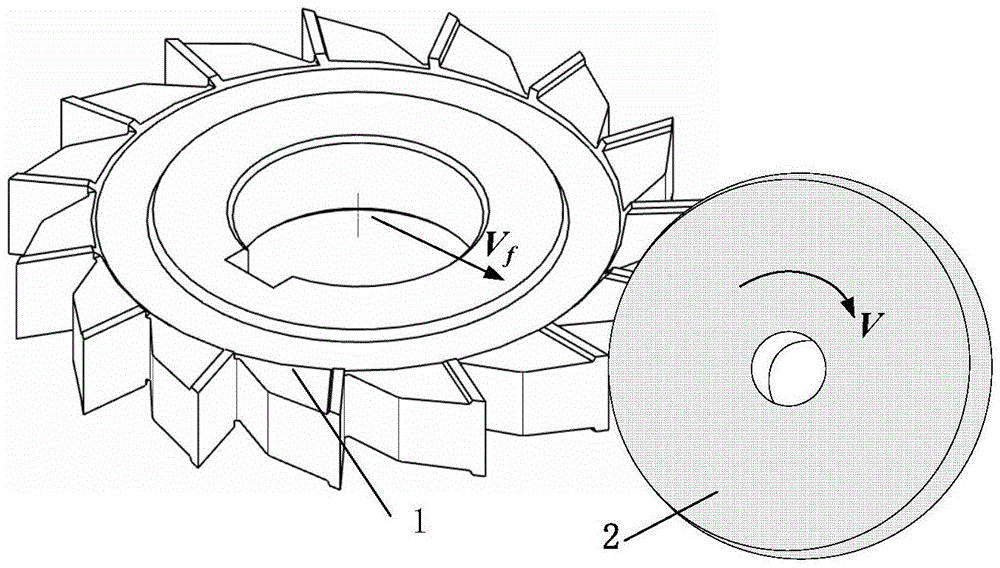
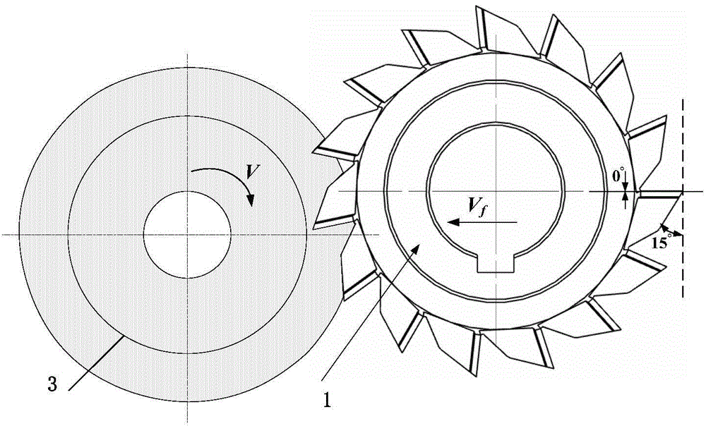
[0042] In order to verify the cutting performance of the present invention's monolithic full-ceramic three-sided edge milling cutter, a comparison test was carried out with a milling cutter of a parameter as an example. The number of teeth of the milling cutter tested was 12, the diameter was 80mm, and the rake angle of the main cutting edge was 0 °, the relief angle is 15°, the relief angle on both sides is 2°, the test plan is milling slot, the cutting speed during the test is 100m / min, the cutting depth is 0.5mm, and the feed rate per tooth is 0.02mm / z, the workpiece material is hardened H13 steel (hardness HRC62), and the comparison tool is a general-purpose cemented carbide side and side milling cutter with the same diameter and the same number of teeth. The results of the comparison test are shown in the table below. , the invented monolithic all-ceramic three-sided edge milling cutter exhibits more excellent cutting performance, its maximum tool flank wear is smaller, a...


PUM

PropertyMeasurementUnit
diameteraaaaaaaaaa
diameteraaaaaaaaaa
diameteraaaaaaaaaa

Abstract

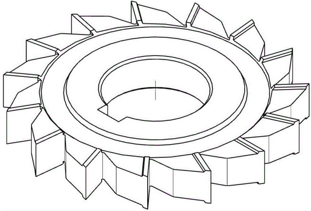
The invention discloses an integral full-ceramic super dense-tooth three-edge milling cutter and a manufacturing method thereof. The integral full-ceramic super dense-tooth three-edge milling cutter comprises a three-edge milling cutter body; the three-edge milling cutter body is connected with a cutter handle through a keyway hole in the center of the three-edge milling cutter body, and comprises a main cutting edge and two side cutting edges; the front angle of the main cutting edge is (-10)-0 degree; the rear angle of the main cutting edge is 5-15 degrees; the rear angles of the two side cutting edges are 2-5 degrees respectively; the three-edge milling cutter body has 10-20 teeth, has a diameter of 50-200 mm, and is made of titanium carbonitride based metal ceramic. Through the adoption of the integral full-ceramic super dense-tooth three-edge milling cutter, high-speed and super high-speed machining can be realized, the material removing rate is improved, and the machining cost is reduced; when the total radial cutting depth remains unchanged, the radial cutting depth of a single cutting edge, the cutting force and the cutter abrasion can be reduced; the service life of the integral full-ceramic super dense-tooth three-edge milling cutter is effectively prolonged, the cutter replacement times are reduced, and the machining efficiency is improved. Compared with an indexable milling cutter, the integral full-ceramic super dense-tooth three-edge milling cutter has the advantages of being high in rigidity, positioning precision, and repeated sharpening property; moreover, the machining quality can be improved, and the machining cost is reduced.

Description

technical field [0001] The invention relates to a cutting tool and a manufacturing method thereof, in particular to an integral all-ceramic ultra-close-tooth three-sided edge milling cutter and a manufacturing method thereof. Background technique [0002] At present, the three-sided milling cutter is a standard tool for machine tools. In addition to the main cutting edge distributed on its circumferential surface, there are secondary cutting edges near the two ends of the outer circle, which improves the cutting conditions and improves processing efficiency and processing quality. The three-sided milling cutter is generally used to process grooves, stepped surfaces or sides. It is not only convenient and flexible to use, but also can expand its scope of use when changing the tool clamping method or the relative position of the tool and the workpiece. For example, side and side milling cutters can be used to mill tines, V-shaped grooves, reamer teeth, ratchets, racks and spli...

Claims


Application Information

Patent Timeline
Patent Type & Authority Applications(China)
IPC IPC(8): B23C5/02C22C29/04
CPCB23C5/02B23C2210/0414C22C29/04
Inventor 刘战强王兵
Owner SHANDONG UNIV
Learn More