
Carbon pollution cleaning method of EUV optical element

A technology for optical components and carbon pollution, applied in chemical instruments and methods, cleaning methods and utensils, cleaning flexible objects, etc., can solve the problems of damaging the surface of optical components, changing the multilayer film structure of EUV optical components, etc., achieving low cost, The effect of less damage and avoiding damage

Inactive Publication Date: 2015-08-12
CHANGCHUN INST OF OPTICS FINE MECHANICS & PHYSICS CHINESE ACAD OF SCI
View PDF5 Cites 4 Cited by
  • Summary
  • Abstract
  • Description
  • Claims
  • Application Information

AI Technical Summary

Problems solved by technology

[0005] In view of this, the purpose of the present invention is to provide a carbon pollution cleaning method for EUV optical components, so as to solve the problems of damaging the surface of optical components and changing the multilayer film structure of EUV optical components in the carbon pollution cleaning process of EUV optical components in the past.

Method used


Image

  • Carbon pollution cleaning method of EUV optical element
  • Carbon pollution cleaning method of EUV optical element
  • Carbon pollution cleaning method of EUV optical element

Examples


Embodiment 1

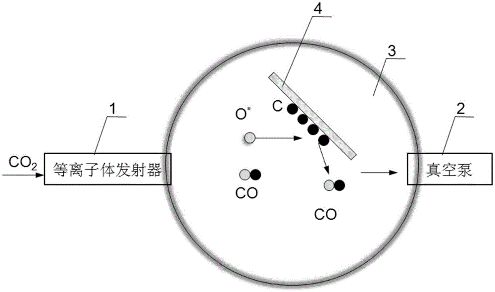
[0033] see figure 1 , where 1 represents the plasma emitter, 2 represents the vacuum pump, 3 represents the cleaning chamber, and 4 represents the optical component sample contaminated by carbon exposure. The specific cleaning process is:

[0034] 1) Put the optical element sample 4 contaminated by carbon exposure into the cleaning chamber 3, and use the vacuum pump 2 to vacuum the cleaning chamber 3, and the vacuum degree is required to reach 10 -5 above mbar;

[0035] 2) Start the plasma emitter 1 and inject carbon dioxide with a supply flow rate of 2 sccm, so that the entire cleaning chamber 3 is filled with plasma carbon dioxide, and the surface carbon-contaminated sample 4 is immersed in the plasma carbon dioxide atmosphere, so that carbon dioxide and The deposited carbon reacts to generate carbon monoxide to realize the cleaning of the optical element sample, and the vacuum pump 2 pumps out the carbon monoxide generated in the cleaning chamber 3 .


PUM


Abstract

The invention provides a carbon pollution cleaning method of an EUV optical element, comprising the following steps: 1) placing the optical element in a cleaning cavity and vacuumizing the cleaning cavity; 2) injecting carbon dioxide in the cleaning cavity via a plasma transmitter to fill the cleaning cavity with the carbon dioxide in a plasma state, and cleaning the carbon pollution through oxidation reaction between the carbon dioxide in the plasma state and deposited carbon on the surface of the optical element. The cleaning method is simple, convenient and low in cost with less harm to the optical element.

Description

technical field [0001] The invention relates to the field of ultra-fine processing of optical elements, and in particular provides a carbon pollution cleaning method for EUV optical elements. Background technique [0002] In extreme ultraviolet (EUV) lithography technology, under the irradiation of EUV light, the hydrocarbons in the system will be cracked to produce free carbon, which will be adsorbed and deposited on the surface of optical components, forming carbon pollution, because carbon can absorb EUV band radiation, the reflectivity is greatly affected, which will greatly affect the working efficiency of the optical system. [0003] In order to prolong the service life of EUV multilayer optical components, the carbon deposition pollution on the surface of optical components should be cleaned in time to restore the reflectivity of optical components. At present, carbon pollution cleaning technologies include plasma oxygen, plasma hydrogen, hydrogen atoms, ozone, etc. ...

Claims


Application Information

Patent Timeline
IPC IPC(8): G03F7/20B08B11/00B08B7/00
Inventor 王依卢启鹏龚学鹏
Owner CHANGCHUN INST OF OPTICS FINE MECHANICS & PHYSICS CHINESE ACAD OF SCI
Learn More