
Cu<2+> and Fe<3+> doped laminar bismuth fluoride lithium ion cell anode material prepared through liquid phase synthesis and preparation method of bismuth fluoride lithium ion cell anode material

A lithium-ion battery, liquid-phase synthesis technology, applied in battery electrodes, secondary batteries, circuits, etc., can solve the problems of harsh process conditions, great influence of electronic transport characteristics, low electronic conductivity, etc., to avoid side reactions product, excellent electrochemical performance, and the effect of high product purity

Active Publication Date: 2015-07-22
嘉兴市燕知网络科技有限公司
View PDF3 Cites 0 Cited by
  • Summary
  • Abstract
  • Description
  • Claims
  • Application Information

AI Technical Summary

Problems solved by technology

The conventional synthesis method of bismuth fluoride is to react with hydrogen fluoride gas and metal oxide / hydroxide or fluorine gas and metal element at high temperature. The process conditions are harsh, the equipment requirements are very high, and the energy consumption is high, so the price is very expensive.
However, the preparation of bismuth fluoride by liquid phase reaction is often unable to be used as a positive electrode material because the by-product content is too high, and it is also uneconomical due to the high cost of waste liquid.
Bismuth fluoride, as a cathode material for lithium-ion secondary batteries, also has a negative characteristic that its electronic conductivity is extremely low, so it will cause a high polarization voltage during charge and discharge.
[0007] In addition, the crystal form and morphology of bismuth fluoride have a great influence on the electron transport characteristics in the crystal lattice, so it is directly related to the electrochemical performance of lithium ion batteries such as charge and discharge speed, capacity and cycle capacity retention; ion doping is a It is an effective way to adjust the microstructure of the lattice and change the electron and ion transport characteristics of the lattice. However, the mechanism of ion doping or even multi-ion synergistic doping on the matrix is ​​very complicated, and the effect is often unpredictable.

Method used


Image

  • Cu&lt;2+&gt; and Fe&lt;3+&gt; doped laminar bismuth fluoride lithium ion cell anode material prepared through liquid phase synthesis and preparation method of bismuth fluoride lithium ion cell anode material
  • Cu&lt;2+&gt; and Fe&lt;3+&gt; doped laminar bismuth fluoride lithium ion cell anode material prepared through liquid phase synthesis and preparation method of bismuth fluoride lithium ion cell anode material

Examples


Embodiment 1

[0018]Embodiment 1: preparation 200mL is composed of 5wt% bismuth nitrate, 1wt% dilute nitric acid, 0.1wt% copper nitrate, 0.1wt% ferric nitrate, 0.1wt% ethanolamine aqueous solution A; preparation 200mL is composed of 15wt% ammonium fluoride, 0.1 Aqueous solution B of polyvinyl alcohol with wt% average molecular weight of 10000-20000; preparation of aqueous solution C consisting of 0.1wt% perfluoroheptanoic acid and 0.1wt% disodium lauryl sulfosuccinic acid monoester; put aqueous solution C into 2L volume , in a cylindrical reactor with an inner diameter of 15 cm to 1 / 3 of the total volume of the reactor, the temperature of the aqueous solution C was set at 40° C. and stirred at a speed of 1250 rpm using a polytetrafluoroethylene stirring paddle with a diameter of 10 cm. Use a peristaltic pump to simultaneously pump the aqueous solution A and the aqueous solution B into the reactor at a speed of 0.1 mL / min until all the prepared aqueous solutions A and B are pumped out. The i...

Embodiment 2

[0019] Embodiment 2: preparation 300mL is composed of 15wt% bismuth nitrate, 0.3wt% copper nitrate, 0.4wt% iron nitrate, 5wt% dilute nitric acid, 0.5wt% aqueous solution A of triethanolamine hydrochloride; preparation 300mL is composed of 45wt% ammonium fluoride , 0.5wt% aqueous solution B of polyvinyl alcohol with an average molecular weight of 10000-20000; the preparation composition is 0.5wt% 2,2-difluorocyclopropanecarboxylic acid and 0.5wt% cocoic acid monoethanolamide sulfosuccinic acid monoester di Sodium aqueous solution C; put aqueous solution C into a cylindrical reactor with a volume of 2L and an inner diameter of 20 cm to 1 / 2 of the total volume of the reactor, set the temperature of aqueous solution C at 60°C and use a cylindrical reactor with a diameter of 15 cm The polytetrafluoroethylene stirring paddle was stirred at a speed of 1500 rpm. Use a peristaltic pump to simultaneously pump the aqueous solution A and the aqueous solution B into the reactor at a rate o...

Embodiment 3

[0020] Example 3: Prepare 250mL of aqueous solution A containing 10wt% bismuth nitrate, 0.2wt% copper nitrate, 0.3wt% ferric nitrate, 3wt% dilute nitric acid, and 0.3wt% triethanolamine; prepare 250mL of 30wt% ammonium fluoride , 0.3wt% op-10 aqueous solution B; the preparation composition is an aqueous solution C of 0.3wt% perfluoroglutaric acid and 0.3wt% potassium monododecyl phosphate; put the aqueous solution C into a 2L volume with an inner diameter of 17 cm In the cylindrical reactor to 2 / 5 of the total volume of the reactor, the temperature of the aqueous solution C was set at 50° C. and stirred at a speed of 1350 rpm using a polytetrafluoroethylene stirring paddle with a diameter of 12 cm. Use a peristaltic pump to simultaneously pump the aqueous solution A and the aqueous solution B into the reactor at a speed of 0.5 mL / min until all the prepared aqueous solutions A and B are pumped out. The inlet of the aqueous solution A into the reactor and the inlet of the aqueou...


PUM


Abstract

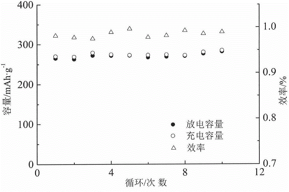
The invention discloses a Cu<2+> and Fe<3+> doped laminar bismuth fluoride lithium ion cell anode material prepared through liquid phase synthesis and a preparation method of the bismuth fluoride lithium ion cell anode material. According to the method, the laminar bismuth fluoride is prepared by taking a liquid phase reaction, designing the technological conditions and introducing a plurality of auxiliaries; the discharge platform voltage and the capacity retention performance of the material are improved by doping Cu<2+> and Fe<3+>; when the bismuth fluoride material is used as the lithium ion cell anode material, the specific capacity of the bismuth fluoride material is higher than 200 mAh / g<-1>. The method is low in equipment requirement, high in product purity, capable of avoiding generation of multiple side reaction products such as double salt of bismuth fluoride in the liquid phase reaction, and excellent in electrochemical performance.

Description

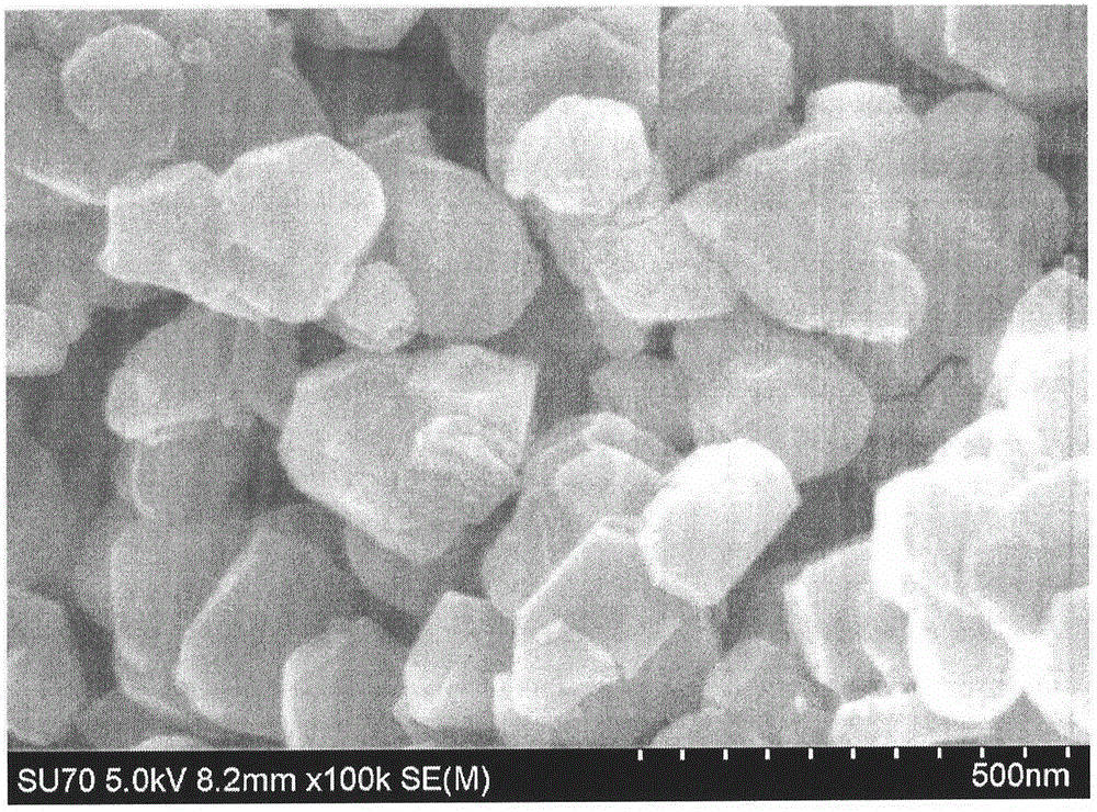
technical field [0001] The invention relates to the technical field of a method for manufacturing a high-capacity bismuth fluoride composite lithium battery cathode material. Background technique [0002] Lithium-ion secondary batteries have the absolute advantages of high volume, weight-to-energy ratio, high voltage, low self-discharge rate, no memory effect, long cycle life, and high power density. Currently, the global mobile power market has an annual share of more than 30 billion US dollars and Gradually grow at a rate of more than 10%. Especially in recent years, with the gradual depletion of fossil energy, new energy sources such as solar energy, wind energy, and biomass energy have gradually become alternatives to traditional energy sources. Among them, wind energy and solar energy are intermittent, and a large amount of energy is used simultaneously to meet the needs of continuous power supply. Energy storage batteries; urban air quality problems caused by automobi...

Claims


Application Information

Patent Timeline
IPC IPC(8): H01M4/136H01M4/1397H01M4/58
CPCH01M4/136H01M4/362H01M4/582H01M4/626H01M10/0525Y02E60/10
Inventor 徐玲霞水淼徐晓萍陈超陈姝舒杰任元龙
Owner 嘉兴市燕知网络科技有限公司
Learn More