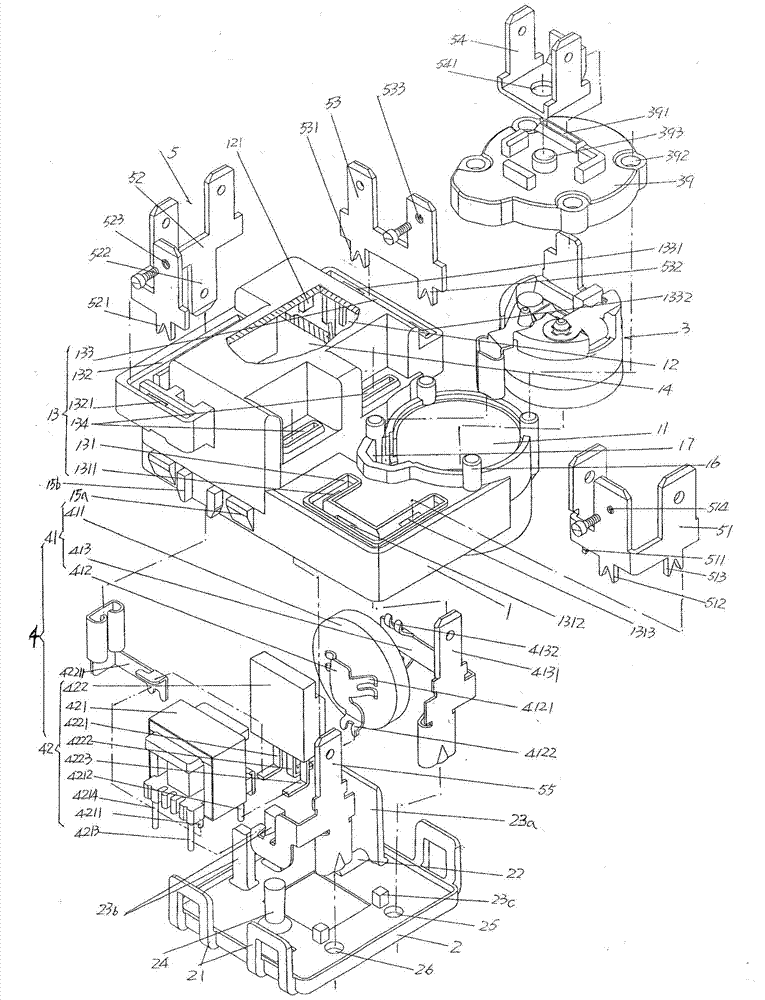
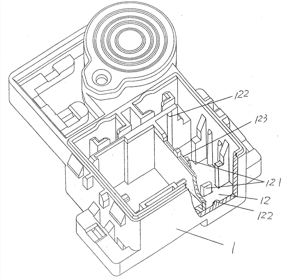
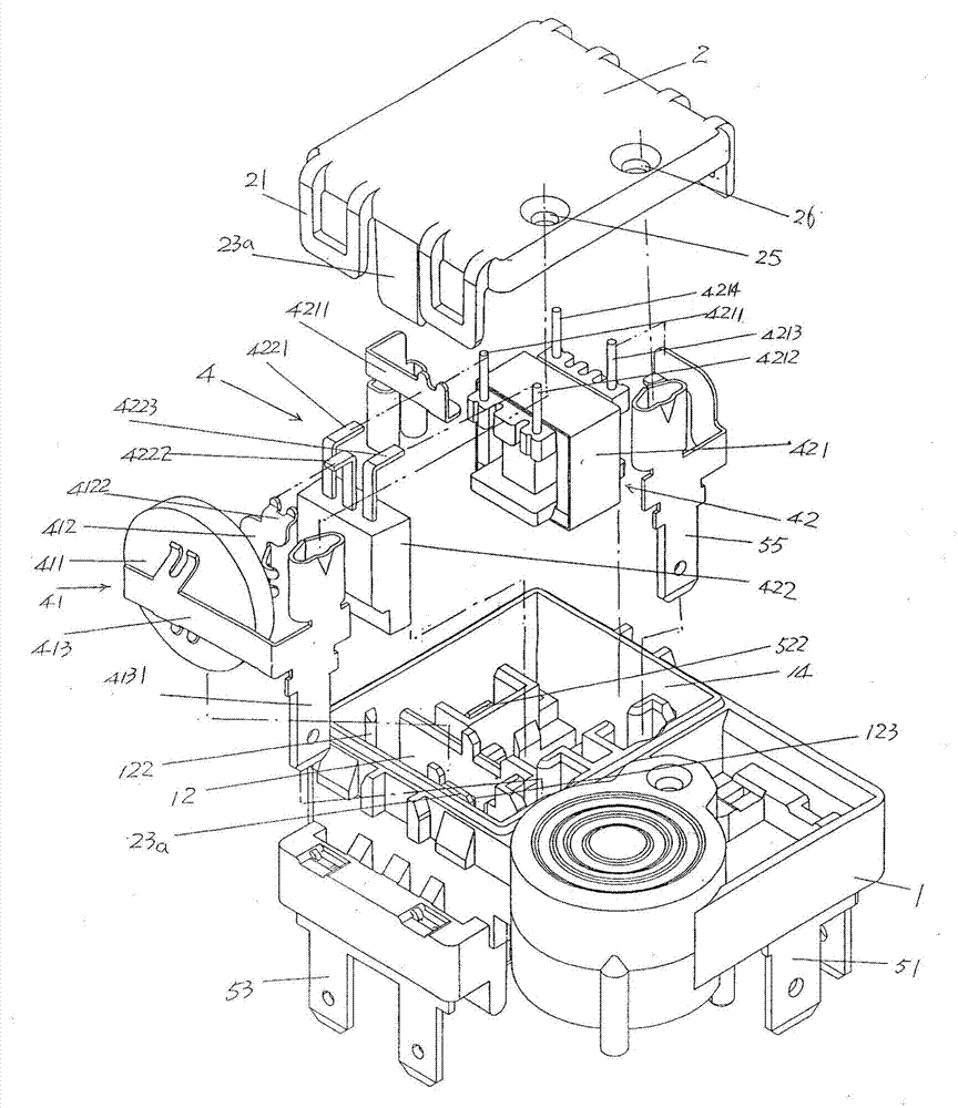
[0007] First of all, as far as the housing is concerned, due to the scattered and disorderly distribution of the external terminal mechanism (also known as the blade mechanism or pin mechanism in the industry) on the housing, it is difficult to reduce the volume of the housing, so that it is impossible to reduce the
impact on the refrigeration compressor. Occupies space, and also affects compact structure, convenient and efficient
assembly, saving
material consumption and reliability in use
In addition, since it is necessary to form six baffles for blocking the pins (including grounding pins, N pins and L pins) on the shell cover and the side facing the housing, and four anti-movement limit stops to prevent the pins from moving Protrusion and five supporting flanges for supporting pins (for details, please refer to
paragraph 2 on page 5 to
paragraph 1 on page 6 of the specification of this patent), thus not only significantly increasing the complexity of the shell structure, but also affecting The installation efficiency of the pins; due to the unreasonable structure of the shell itself, the pins (ie ground pins, N pins and L pins) must be assembled before the shell cover is fitted to the shell, that is to say, the pins must be assembled first. Insert them into the corresponding pin slots (that is, pin holes) preset on the case cover, and then fit the case cover together with the pins with the housing, so the
assembly efficiency will be seriously affected, because pre-installing the pins on the case cover will The shell cover interferes with the shell, and the stability of the pins is difficult to guarantee, and there is a risk of deflection and looseness
[0008] Secondly, as far as the starter is concerned, one, although contacting both sides of the bottom of the PTC
thermistor with the top protrusion can significantly reduce the PTC
thermistor in the case. The supporting area in the cavity can significantly reduce the volume of the
positive temperature coefficient
thermistor, for example, the weight is reduced from 35-40g to 15-16g, but because the circumferential side edge of the
positive temperature coefficient thermistor still needs It is in contact with the wall of the
positive temperature coefficient thermistor cavity in a large area, so it is not enough to reflect the ultimate energy-saving effect. The specific performance is that the volume of the positive
temperature coefficient thermistor is still relatively large, and the weight (15-16g) still biased
Theoretically speaking, forming a support wall on the corresponding
cavity wall of the positive
temperature coefficient thermistor cavity and forming a protrusion on the support wall can make up for the above-mentioned deficiency, so that the volume of the positive
temperature coefficient thermistor can be further reduced, The weight can be further reduced and the energy-saving effect can be reflected to the extreme degree, but repeated experiments by the applicant show that this idea is not advisable, because on the one hand, the aforementioned first and second pins and the positive temperature coefficient thermistor On the other hand, the installation of the starter is troublesome due to excessive occupation of the space of the PTC thermistor cavity; The structure of a pair of support walls themselves is relatively complicated, which leads to a relatively complicated mold for manufacturing the shell; third, because the top protrusion is formed on the support wall, the bottom of the positive temperature coefficient thermistor, that is, the bottom surface, is in direct contact with the positive temperature The distance between the cavity bottom of the coefficient thermistor cavity is the sum of the height of the support wall and the height of the top protrusion, so there is a situation where the positive temperature coefficient thermistor is raised too much, so that the positive temperature coefficient thermistor The positive temperature coefficient thermistor cavity protrudes from the upper part of the device, and the protruding part needs to be compensated by the raised cavity on the cover (the protruding part penetrates into the raised cavity). On the one hand, it increases the complexity of the cover, and on the other hand On the one hand, the contact area between the positive temperature coefficient thermistor and the raised cavity is increased, and on the other hand, in order to ensure that the first and second pins (the first pin is essentially the first contact piece, and the second pin is essentially the second The contact piece, the same below) in the middle position corresponding to the surface of both sides of the positive temperature coefficient thermistor to reliably hold the positive temperature coefficient thermistor and the position of the first and second pins must be moved upwards, so that the first , The supporting point between the second pin and the
cavity wall of the positive temperature coefficient thermistor cavity (the part in contact with the support of the
cavity wall) is moved to the upper cavity of the positive temperature coefficient thermistor cavity, so that the installation of the entire starter Stabilization effects have an
impact, for example, the first and second pins are in danger of breaking free from the positive temperature coefficient thermistor cavity, resulting in failure of electrical contact between the first and second pins and the positive temperature coefficient thermistor
Of course, by increasing the size of the housing in the height direction and thereby deepening the depth of the PTC thermistor cavity, the PTC thermistor can be located in the PTC thermistor cavity as a whole and can make up for the aforementioned disadvantages. Factors, but such a design will significantly increase the volume of the housing, that is, the problem of losing
sight of the other; Fourth, because the first pin is in contact with the first pin reed on one side of the positive temperature coefficient thermistor, that is, the first contact Leaf reed (the patent is called the first spring) and the second prong is in contact with the surface of the other side of the positive temperature coefficient thermistor, that is, the second contact reed (the patent is called the second spring) All contact with the surface of the positive temperature coefficient thermistor in a straight line, that is, the first and second pin reeds are both horizontally parallel to each other and fully correspond to each other, so when the
electric spark is generated, the positive temperature coefficient thermistor There will be many cracks, because the opposite sides are still elastically supported by the corresponding first and second pin reeds, and the cracked (cracked) part of the elastically supported positive temperature coefficient thermistor continues to be stable The ground is clamped in place while the remaining fragments scatter, so power continues through the resiliently supported remnants of the PTC thermistor, causing these remnants and their associated first and second The two-pin reeds melt each other, and then produce an
alloy that exhibits a certain
conductivity. As a result, an electrical
short circuit is formed between the first and second prong reeds, which in turn further accelerates the abnormal
heat generation. Generated, it is very likely to force further failure of the device, such as causing
softening and deformation of the shell, etc.
[0009] In addition, as far as the overload protector is concerned, firstly, because the fixed seat only has a pin cavity for the spring piece and the pin (the patent is called the first pin) to accommodate, so when the spring plate and the pin are accommodated in the pin cavity, , the positioning effect of the fixing seat on the spring piece and the pin is fragile, so once there is a loose displacement, it will affect the electrical contact or disconnection effect between the moving contact on the spring piece and the static contact on the pin
Second, since the heating wire cavity formed on the fixing seat is only for accommodating the heating wire, it has no limiting effect on the heating wire, and there will be arching in the
actual use process, which will affect the effect of the
bimetal sheet and its overall contact


