
Novel nitride quantum well infrared detector and manufacturing method thereof

An infrared detector and quantum well technology, applied in the field of infrared detectors, can solve the problems of poor crystal quality of nitride materials, reduced signal-to-noise ratio, unfavorable for photocurrent signal extraction, etc., and achieves the effect of reducing adverse effects and efficiently extracting

Active Publication Date: 2015-06-24
PEKING UNIV
View PDF8 Cites 13 Cited by
  • Summary
  • Abstract
  • Description
  • Claims
  • Application Information

AI Technical Summary

Problems solved by technology

Due to the large lattice mismatch and thermal mismatch between the epitaxial film and the substrate, the crystal quality of the nitride material prepared by heteroepitaxy is poor, and the dislocation density can reach 10 7 -10 9 cm -2 magnitude, forming a high-density dark current channel, which is not conducive to the extraction of photocurrent signals
At the same time, the inherent spontaneous polarization of the nitride material system and the built-in electric field (polarization field) induced by the piezoelectric polarization inhibit the longitudinal transport of carriers, greatly reducing the signal-to-noise ratio

Method used


Image

  • Novel nitride quantum well infrared detector and manufacturing method thereof
  • Novel nitride quantum well infrared detector and manufacturing method thereof
  • Novel nitride quantum well infrared detector and manufacturing method thereof

Examples


Embodiment Construction

[0034] The present invention will be further described through the embodiments below in conjunction with the accompanying drawings.

[0035] In this example, prepare 10 cycles of Al 0.3 Ga 0.7 N / GaN quantum well infrared detector.

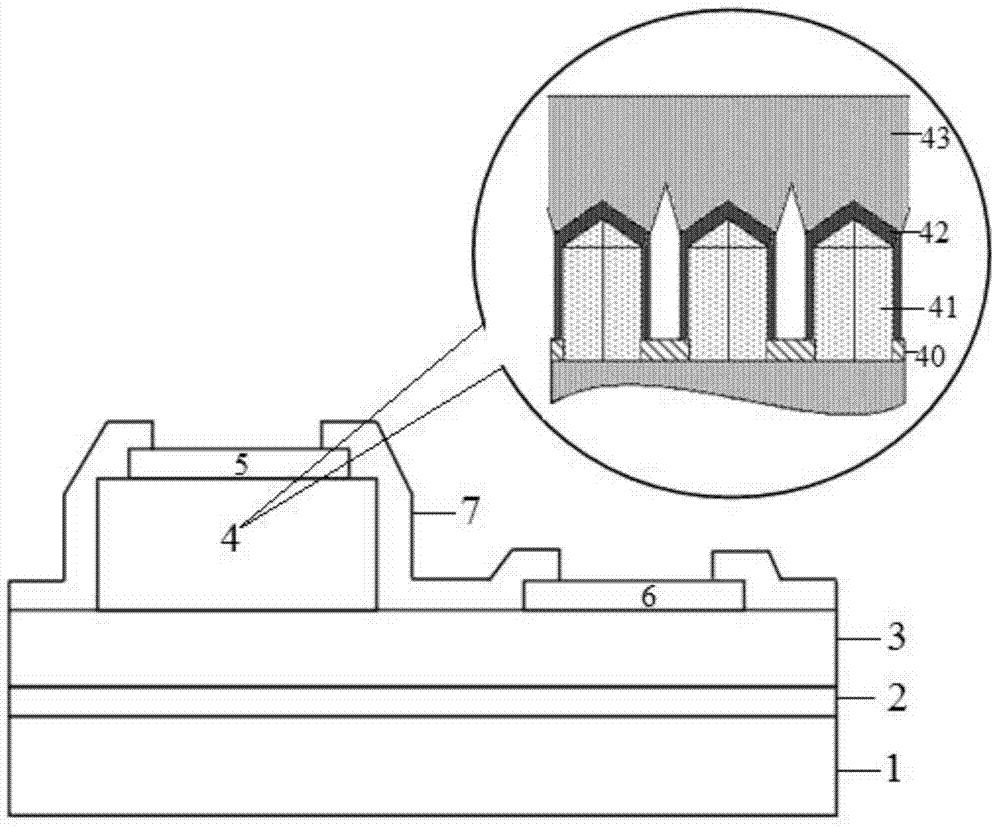
[0036] like figure 1 As shown, the quantum well infrared detector of the present embodiment comprises: substrate 1, buffer layer 2, bottom electrode contact layer 3, compound layer 4, top electrode 5, bottom electrode 6 and passivation layer 7; On substrate 1 Growing a buffer layer 2; growing a bottom electrode contact layer 3 on the buffer layer 2; a composite layer 4 and a top electrode 5 on a part of the bottom electrode contact layer 3; a bottom electrode 6 on a part of the bottom electrode contact layer 3; The sides of the top electrode 5 and the bottom electrode 6 are covered with a passivation layer 7 ; wherein, the composite layer 4 includes: a mask layer 40 , a nanopillar array 41 , multiple quantum wells 42 and a top electrode contact ...


PUM

PropertyMeasurementUnit
Diameteraaaaaaaaaa
Thicknessaaaaaaaaaa

Abstract

The invention discloses a novel nitride quantum well infrared detector and a manufacturing method thereof. According to the quantum well infrared detector, a mask layer on a substrate is provided with hole structures distributed periodically, nanopillar arrays grow from holes, multiple quantum wells grow on the tops and the side faces of the nanopillar arrays, the multiple quantum wells corresponding to the tops are semi-polar face multiple quantum wells, and the multiple quantum wells corresponding to the side faces are nonpolar face multiple quantum wells. The multiple quantum wells grow on the nanopillar arrays with extremely low dislocation density, so a multiple quantum well structure with extremely high crystal quality can be achieved; the polarized field intensity of the semi-polar face multiple quantum wells and the nonpolar face multiple quantum wells is far below that of traditional polar face multiple quantum wells, so extraction of efficient photo-electric signals can be achieved; photoelectric responses occur on the surface of the front incidence detector, and the process of manufacturing a surface grating structure for a traditional quantum well infrared detector or conducting end face 45-degree polishing on the traditional quantum well infrared detector is omitted; third-generation semiconductor materials are adopted for multiple quantum well materials, photon detection of a full infrared spectroscopy window can be achieved, and application prospects are broad.

Description

technical field [0001] The invention relates to infrared detector technology, in particular to a novel nitride quantum well infrared detector and a preparation method thereof. Background technique [0002] Quantum well infrared detectors are detectors made of semiconductor multi-quantum wells or superlattice materials with intersubband transitions. They have the advantages of good stability, fast response, radiation resistance, and easy fabrication of large-area focal plane arrays. Traditional quantum well infrared detectors and their large-scale arrays have been realized in the first-generation semiconductors (Si, Ge) and second-generation semiconductors (Group III arsenide semiconductors), and have great potential in military and civilian fields such as precision guidance and infrared imaging. Extremely wide range of applications. However, due to the limitation of the bandgap coverage of its materials, the existing quantum well infrared detectors can only meet the detecti...

Claims


Application Information

Patent Timeline
IPC IPC(8): H01L31/101H01L31/0352H01L31/18
CPCY02P70/50
Inventor 王新强荣新沈波陈广郑显通王平许福军秦志新
Owner PEKING UNIV
Learn More