
Negative image treatment-free lithograph plate

A processing-free, lithographic technology, applied in the field of negative-image processing-free lithographic printing plates and processing-free lithographic printing plates on printing presses, can solve problems such as insufficient print durability, and achieve improved print durability and strong adsorption. , the effect of improved wear resistance and chemical resistance

Active Publication Date: 2015-06-24
LUCKY HUAGUANG GRAPHICS +1
View PDF9 Cites 14 Cited by
  • Summary
  • Abstract
  • Description
  • Claims
  • Application Information

AI Technical Summary

Problems solved by technology

Although this method achieves a better balance between on-press developing performance and fountain solution contamination, and improves the printing durability to a certain extent, compared with the requirements of long printing runs, the printing durability is still far from enough

Method used


Image

  • Negative image treatment-free lithograph plate
  • Negative image treatment-free lithograph plate
  • Negative image treatment-free lithograph plate

Examples


Synthetic example 1

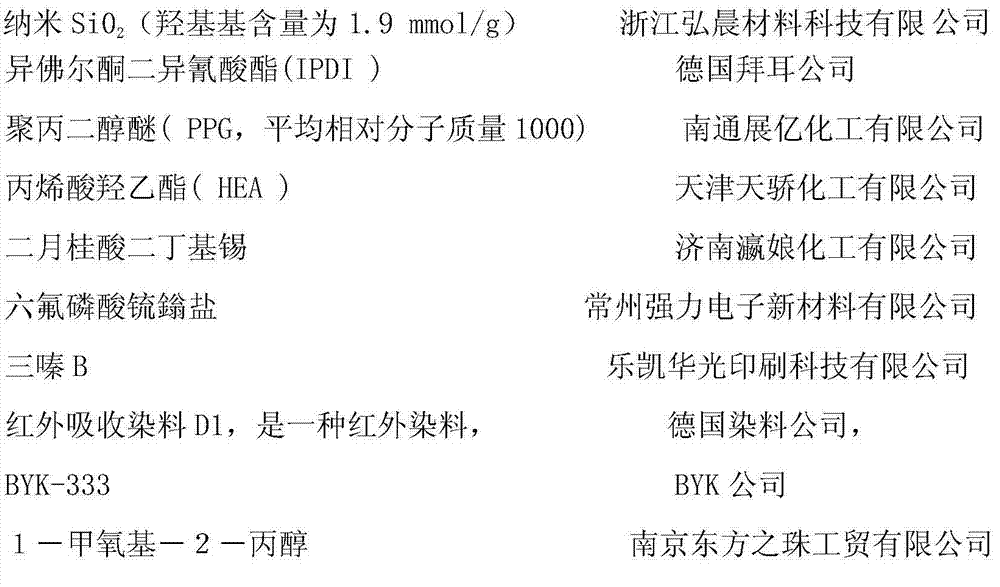
[0063] 100 grams of IPDI, 7.6 grams of nano-SiO with a diameter of 50nm 2 (hydroxyl value 1.9mmol / g) and 1g of dibutyltin dilaurate catalyst were added to a 500mL four-neck flask equipped with a thermometer, stirrer and nitrogen gas introduction device, and the 2 Stir and react at 60°C for 8 hours under protection, use the chemical titration method to determine that the -NCO content will no longer decrease, add 220 grams of PPG, wait for the temperature reaction to reduce the -NCO content to 45%, add 51.4 grams of HEA, and measure it by infrared spectroscopy 2235cm-NCO characteristic absorption peak disappears completely. Obtain about 380.0 g SiO 2 / Urethane Acrylic Prepolymer B1.

Synthetic example 2

[0065] 100 grams of IPDI, 19.0 grams of nano-SiO with a diameter of 10nm 2 Add 1g of dibutyltin dilaurate catalyst into a 500mL four-neck flask equipped with a thermometer, stirrer and nitrogen gas introduction device, under N 2 Stir and react at 60°C for 8 hours under protection, use chemical titration to determine that the -NCO content does not drop anymore, add 216.0 grams of PPG, wait for the temperature reaction to reduce the -NCO content to 45%, add 50.0 grams of HEA, and measure by infrared spectroscopy 2235cm-NCO characteristic absorption peak disappears completely. Obtain about 385.0 g of SiO 2 / Urethane Acrylic Prepolymer B2.

Synthetic example 3

[0067] 100 grams of IPDI, 1.9 grams of nano-SiO with a diameter of 100nm 2 (hydroxyl value 1.9mmol / g) and 1g of dibutyltin dilaurate catalyst were added to a 500mL four-neck flask equipped with a thermometer, stirrer and nitrogen gas introduction device, and the 2 Stir and react at 60°C for 8 hours under protection, use the chemical titration method to determine that the -NCO content will no longer decrease, add 224 grams of PPG, wait for the temperature reaction to reduce the -NCO content to 45%, add 52 grams of HEA, and use infrared spectroscopy to determine 2235cm-NCO characteristic absorption peak disappears completely. Obtain about 378.0 g SiO 2 / Urethane Acrylic Prepolymer B2.


PUM

PropertyMeasurementUnit
particle sizeaaaaaaaaaa
thicknessaaaaaaaaaa
glass transition temperatureaaaaaaaaaa

Abstract

The invention provides a negative image treatment-free lithograph plate. The lithograph plate comprises a base, an imaging layer on the base and a protective layer on the imaging layer, wherein the imaging layer includes a polymer binder, an initiation system capable of initiating polymerization / cross-linking during imaging exposure and polymerisable / cross-linkable components, and the polymerisable / cross-linkable components comprise nanometer SiO2 / polyurethane acrylate prepolymer. The treatment-free lithograph plate can be directly installed on a printing machine for printing without developing after infrared laser scanning exposure. With the treatment-free lithograph plate and a printing method provided by the invention, the disadvantage of insufficient pressrun of treatment-free lithograph plates prepared by other methods is overcome, high pressrun is realized while high quality dots are guaranteed, and the number of transferring paper in starting of a machine is reduced.

Description

technical field [0001] The invention relates to a lithographic printing plate premise and a printing method, in particular to a negative image processing-free lithographic printing plate and a printing method of the processing-free lithographic printing plate on a printing machine. Background technique [0002] The preparation of lithographic printing plates is well known in the printing industry. The plate-making process of the lithographic plate requires at least two steps to complete. One is to expose the plate coated with the photosensitive composition to a specific light source through a mask (such as a positive film type and a negative film type mask), thereby forming One is the latent image of the light image; the other is to carry out a so-called subsequent development step on the exposed printing plate, through which the excess coating is removed. Pre-coated photosensitive lithography is a sheet-like material supported by aluminum or polyester, and can be prepared ...

Claims


Application Information

Patent Timeline
Patent Type & Authority Applications(China)
IPC IPC(8): G03F7/09G03F7/004G03F7/033
Inventor 杨青海张刚宋小伟吴兆阳黄文明刘东黎吴俊君刘红来
Owner LUCKY HUAGUANG GRAPHICS
Learn More