
A kind of manufacturing method of wireless radio frequency remote optical cable, electric cable and photoelectric composite cable for communication

A technology of radio frequency and manufacturing method, which is applied in the manufacture of cables/conductors, power cables including optical transmission elements, power cables, etc., can solve problems such as poor effect, unsatisfactory solar radiation resistance, and unsatisfactory softness performance. , to achieve the effect of simple structure, high qualified rate of finished products and strong resistance to solar radiation

Inactive Publication Date: 2017-12-01
扬州市红旗电缆制造有限公司
View PDF8 Cites 0 Cited by
  • Summary
  • Abstract
  • Description
  • Claims
  • Application Information

AI Technical Summary

Problems solved by technology

[0003] At home and abroad, there have been cases of research and development and use of remote optical cables and cables. However, the remote optical cables in the prior art are not effective in indoor and outdoor environments, the anti-sunlight radiation ability is not ideal, and the soft performance cannot meet the requirements.

Method used


Image

  • A kind of manufacturing method of wireless radio frequency remote optical cable, electric cable and photoelectric composite cable for communication
  • A kind of manufacturing method of wireless radio frequency remote optical cable, electric cable and photoelectric composite cable for communication
  • A kind of manufacturing method of wireless radio frequency remote optical cable, electric cable and photoelectric composite cable for communication

Examples


Embodiment 1

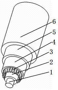
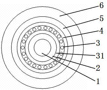
[0027] please see figure 1 with figure 2 , a wireless radio frequency remote optical cable for communication, characterized in that it consists of a central strength member 1 extruded with a plastic layer 2, an inner cushion 31 located outside the plastic layer 2, an outer cushion 4 located outside the inner cushion, and an inner cushion 4 located outside the inner cushion. The light transmission body 3 between the cushion layer and the outer cushion layer, the protective layer 5 located outside the outer cushion layer, and the outer sheath 6 coated outside the protective layer by extrusion; the inner cushion layer is close to the plastic layer, and the light transmission The body is distributed between the inner cushion layer and the outer cushion layer, and only one layer of light transmission body can be placed in the gap between the inner cushion layer and the outer cushion layer, and the protective layer is close to the outer cushion layer; the central reinforcement is m...

Embodiment 2

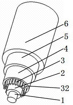
[0056] please see image 3 with Figure 4 , wireless radio frequency remote optical cable for communication, basic implementation example 1, the difference is: the inner cushion and the outer cushion are connected by two connecting bars 32, and the optical transmission body is located between the inner cushion and the outer cushion In the gap between them, the inner cushion layer, the connecting strip and the outer cushion layer can be integrally formed by extrusion.

[0057] Of course, it can also be the wireless remote radio cable and photoelectric composite cable as in the embodiment 1.

Embodiment 3

[0059] please see Figure 5 with Image 6 , wireless radio frequency remote optical cable for communication, basic implementation example 2, the difference is: the inner cushion and the outer cushion are connected by four connecting bars 32, and the optical transmission body is located between the inner cushion and the outer cushion In the gap between them, the inner cushion layer, the connecting strip and the outer cushion layer can be integrally formed by extrusion.

[0060] Of course, it can also be the wireless remote radio cable and photoelectric composite cable as in the embodiment 1.

[0061] Of course, the inner cushion layer and the outer cushion layer can also be connected through other multiple connecting bars, which can realize flexible distribution of optical transmission body and / or power distribution.

[0062] The wireless radio remote optical cable for communication, the radio remote remote cable or the radio radio remote photoelectric composite cable describ...


PUM

PropertyMeasurementUnit
lengthaaaaaaaaaa

Abstract

The invention belongs to the technical field of cables, and particularly relates to a manufacturing method for a wireless radio frequency pull-far optical cable for communication. The method is characterized in that the method includes the steps of manufacturing a plastic layer, manufacturing an inner cushion layer, manufacturing an outer cushion layer and manufacturing an outer protecting bush. The invention further discloses a wireless radio frequency pull-far cable manufacturing method and a wireless radio frequency pull-far optical-electric composite cable manufacturing method. The cables have the advantages of being simple in structure, easy to manufacture, universal in the indoor environment and the outdoor environment, perfect in bending-resistant performance, softer, easier to construct and high in solar-radiation-resistant capacity. The manufacturing methods are simple and easy to master, and the percent of pass of the manufactured finished cable products is high.

Description

technical field [0001] The invention belongs to the technical field of cables, and in particular relates to a radio frequency remote optical cable for communication, a manufacturing method of an electric cable and a photoelectric composite cable. Background technique [0002] In the base station signal transmission system, the cable from the baseband unit BBU to the remote radio unit RRU is called a wireless radio cable, and the optical cable that provides signal transmission for the RRU is called a remote radio cable. The optical cable for radio frequency pull is mainly used in the local remote at the same base station, and the length is usually 100 to 300 meters. When a longer distance is required, it is advisable to use an outdoor optical cable for connection, and then connect the current end to the wireless radio remote Use fiber optic cable. Similarly, the length of the cable that provides power to the base station is generally about 200 meters. This kind of cable is c...

Claims


Application Information

Patent Timeline
Patent Type & Authority Patents(China)
IPC IPC(8): G02B6/44H01B13/00H01B7/17H01B7/18H01B9/00H01B7/04
CPCG02B6/443G02B6/4432G02B6/4479H01B7/04H01B7/17H01B9/005H01B13/00
Inventor 陈冠瑜曾广彬胡仕国王仕俊吴连飞陈辉吴连君张顶松胡仕朗王娟
Owner 扬州市红旗电缆制造有限公司
Learn More